
Printing and dyeing wastewater denitrifying technology

A technology for printing and dyeing wastewater and denitrification, which is used in aerobic and anaerobic process treatment, water pollutants, water/sludge/sewage treatment, etc., and can solve the problems of large flow, high construction cost and short reaction time.

Pending Publication Date: 2018-05-15
SHAOXING WATER TREATMENT DEV
View PDF7 Cites 2 Cited by
  • Summary
  • Abstract
  • Description
  • Claims
  • Application Information

AI Technical Summary

Problems solved by technology

There are three commonly used denitrification methods: the first is the oxidation ditch structure, which divides the treatment tank into an aerated area and a non-aerated area, but because the single overflow reaction time in the non-aerated area is very short, the The nitrification reaction is sufficient but the denitrification reaction in the aeration zone is not sufficient, and the total nitrogen removal rate is generally 40-50%; The sewage and wastewater are used as the carbon source, the flow rate is relatively large, the requirements for the inner diameter of the pipeline are relatively high, and the construction cost is high; the third is to set up a denitrification zone after the sewage and wastewater aeration treatment system, but this method requires an additional denitrification carbon source , higher processing cost

Method used


Image

  • Printing and dyeing wastewater denitrifying technology
  • Printing and dyeing wastewater denitrifying technology
  • Printing and dyeing wastewater denitrifying technology

Examples


Embodiment 1

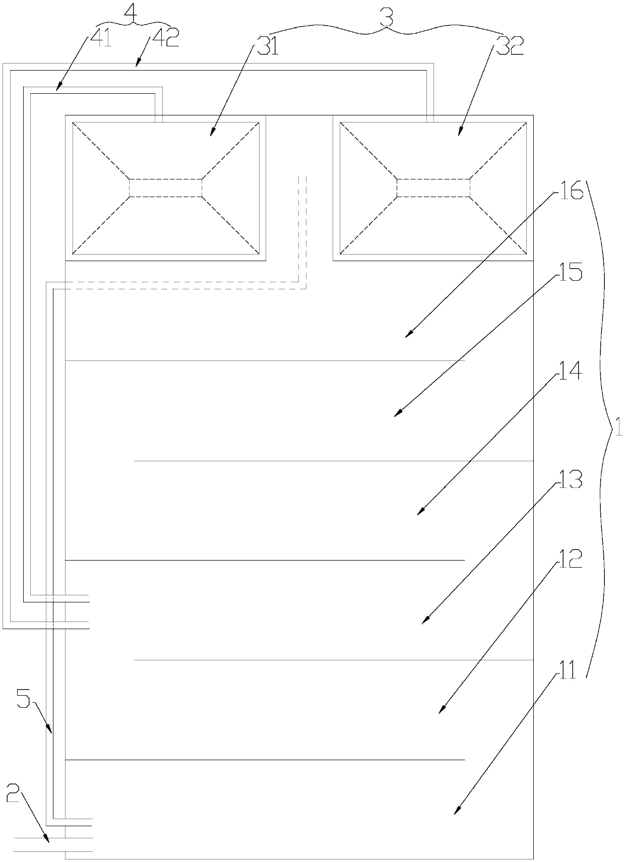
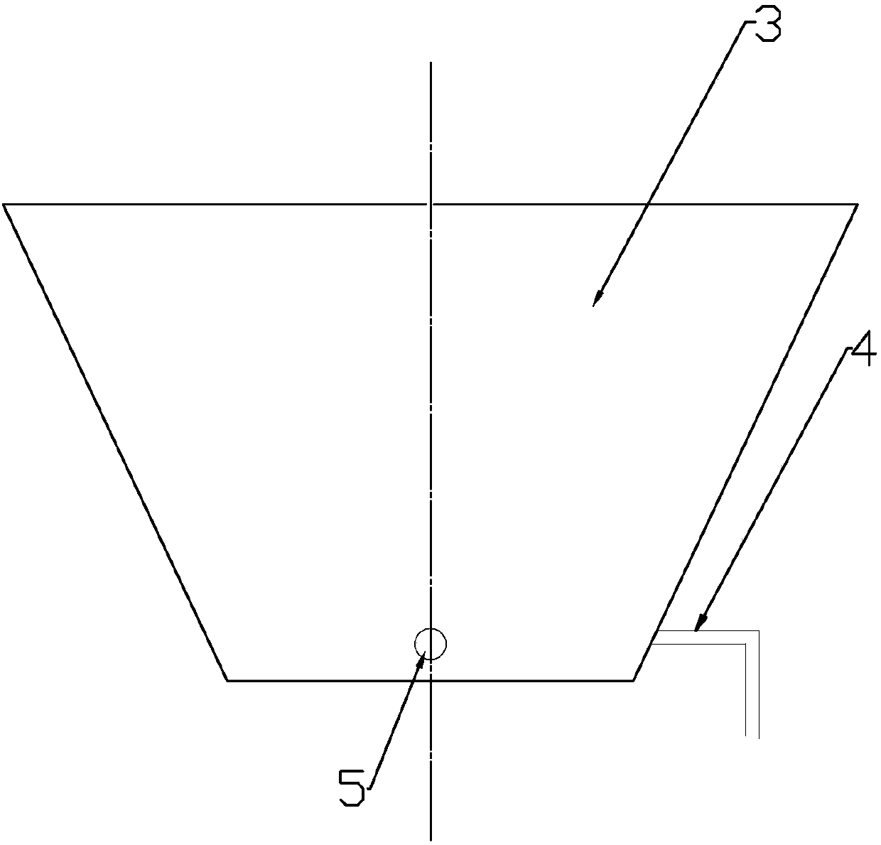
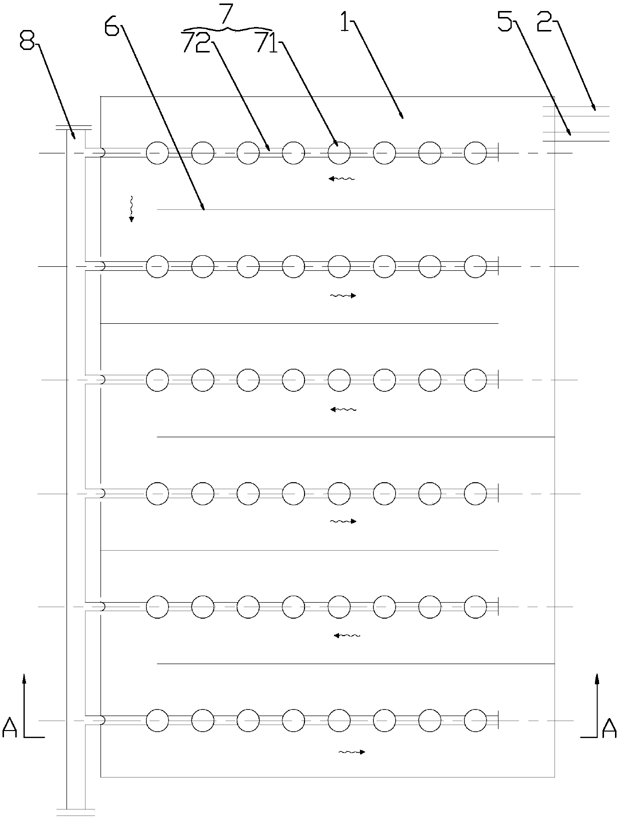
[0021] In this embodiment, a printing and dyeing wastewater denitrification process includes a treatment tank 1 and a sedimentation tank 3. The sedimentation tank 3 is located at the end of the treatment tank 1. Two anaerobic zones are sequentially arranged in the treatment tank 1, namely anaerobic zone-11 and anaerobic zone-11. Oxygen zone two 12, and four aeration zones, i.e. aeration zone one 13, aeration zone two 14, aeration zone three 15 and aeration zone four 16, anaerobic zone one 11, anaerobic zone two 12, aeration zone two Gas zone 13, aeration zone 2 14, aeration zone 3 15 and aeration zone 4 16 are connected end to end in sequence, the tail end of anaerobic zone 11 is connected with the head end of anaerobic zone 2 12, anaerobic zone 2 12 The tail end of the aeration zone 13 is connected with the head end of the aeration zone one 13, the tail end of the aeration zone one 13 is connected with the head end of the aeration zone two 14, the tail end of the aeration zone...


PUM


Abstract

The invention relates to a printing and dyeing wastewater denitrifying technology, and belongs to the technical field of biological treatment to water, wastewater or sewage. In the printing and dyeingwastewater denitrifying technology, a treatment tank and a sedimentation tank are used, wherein the sedimentation tank is positioned at the tail end of the treatment tank; two anaerobic zones and four aeration zones are sequentially arranged inside the treatment tank; a water inlet of the treatment tank is formed in the anaerobic zones; a reflowing pipe is arranged inside the sedimentation tank;the other end of the reflowing pipe is connected to a starting position of the aeration zones; the anaerobic zones have the dissolved oxygen content of 0.2 mg / L or below; the aeration zones have the dissolved oxygen content of 2.0-4.0 mg / L; water to be treated is sequentially treated by the two anaerobic zones, then enters the aeration zones together with reflowing sludge so as to complete aeration, then is sent into sedimentation tank, is sedimentated and then is discharged. After being applied to printing and dyeing wastewater treatment, the printing and dyeing wastewater denitrifying technology has the beneficial effects of low cost, high carbon source utilization rate and the like.

Description

technical field [0001] The application relates to a process for denitrification of printing and dyeing wastewater, which belongs to the technical field of biological treatment of water, wastewater or sewage. Background technique [0002] Printing and dyeing wastewater usually contains NO 3 - , NH 4 + , the existence of these ions will affect the total nitrogen content of the discharged wastewater. If the total nitrogen content is too high, it will cause eutrophication of the water body. Therefore, denitrification treatment is usually carried out during the treatment process. There are three commonly used denitrification methods: the first is the oxidation ditch structure, which divides the treatment tank into an aerated area and a non-aerated area, but because the single overflow reaction time in the non-aerated area is very short, the The nitrification reaction is sufficient but the denitrification reaction in the aeration zone is not sufficient, and the total nitrogen ...

Claims


Application Information

Patent Timeline
Patent Type & Authority Applications(China)
IPC IPC(8): C02F3/30C02F101/16
CPCC02F3/30C02F2101/16C02F2301/046
Inventor 劳红标曹祺奚晓东宋华龙
Owner SHAOXING WATER TREATMENT DEV
Learn More