Visual sensor system used for dry cell slurry layer paper winding defect detection and method thereof

A vision sensor and defect detection technology, applied in the field of vision sensors, can solve the problems of low reliability and efficiency of artificial vision methods, limited shooting angle of machine vision methods, etc., and achieve strong anti-interference ability, improved contrast ratio, and simple system structure Effect

Pending Publication Date: 2018-05-15
SOUTH CHINA UNIV OF TECH
View PDF0 Cites 11 Cited by
  • Summary
  • Abstract
  • Description
  • Claims
  • Application Information

AI Technical Summary

Problems solved by technology

[0004] The purpose of the present invention is to solve the above-mentioned defects in the prior art, and provide a visual sensor system and method for detecting the winding defect of dry battery pulp paper, aiming to solv

Method used


Image

  • Visual sensor system used for dry cell slurry layer paper winding defect detection and method thereof
  • Visual sensor system used for dry cell slurry layer paper winding defect detection and method thereof
  • Visual sensor system used for dry cell slurry layer paper winding defect detection and method thereof

Examples


Embodiment 1

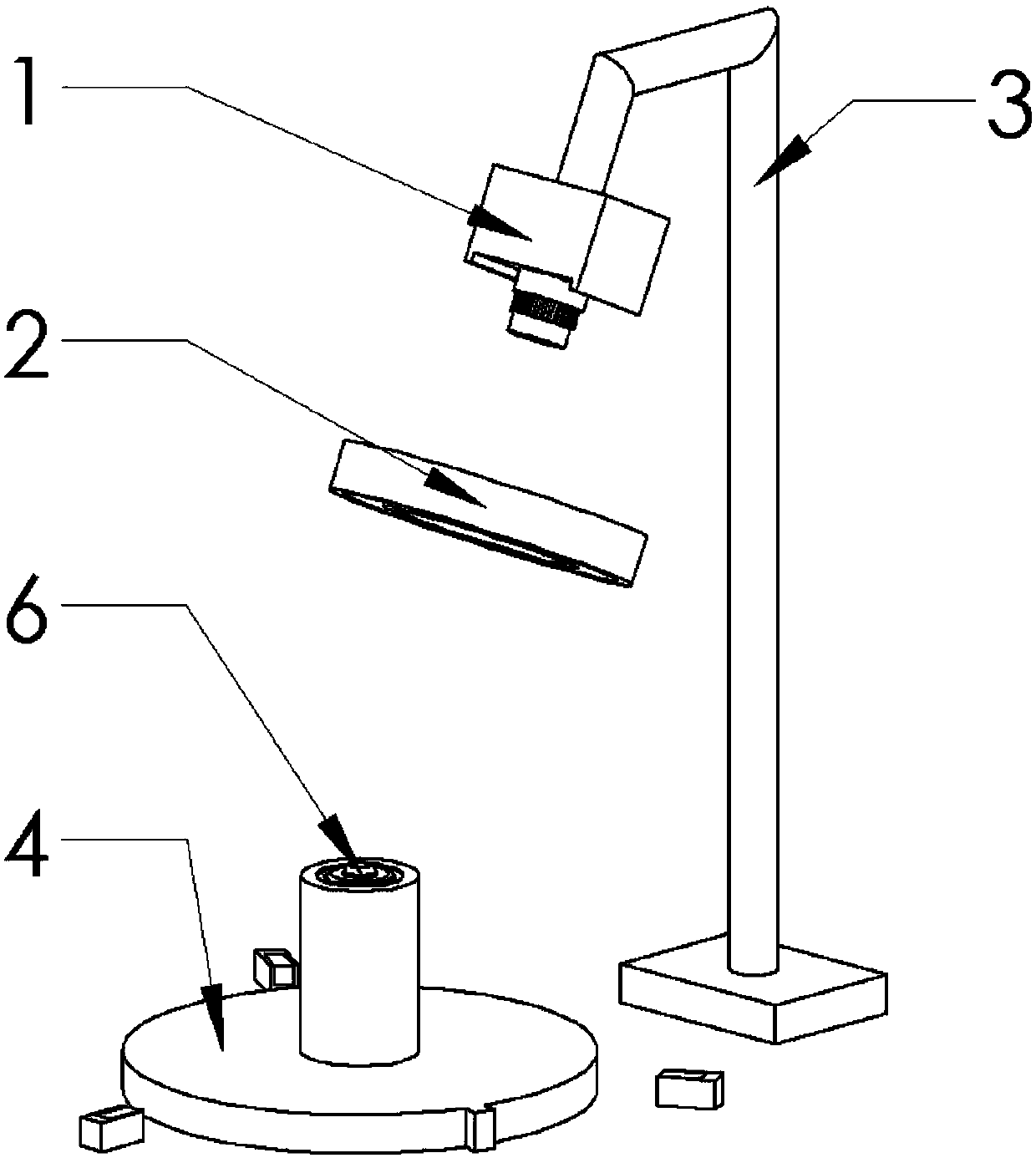
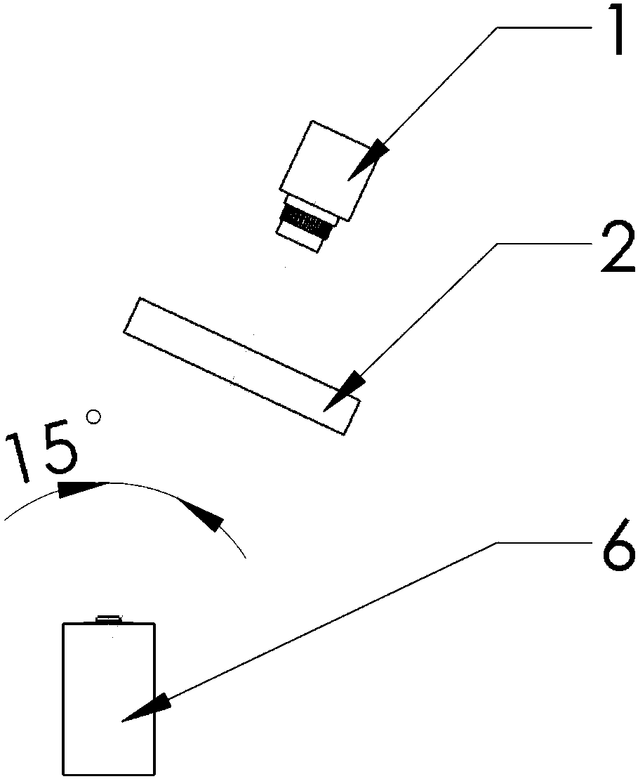
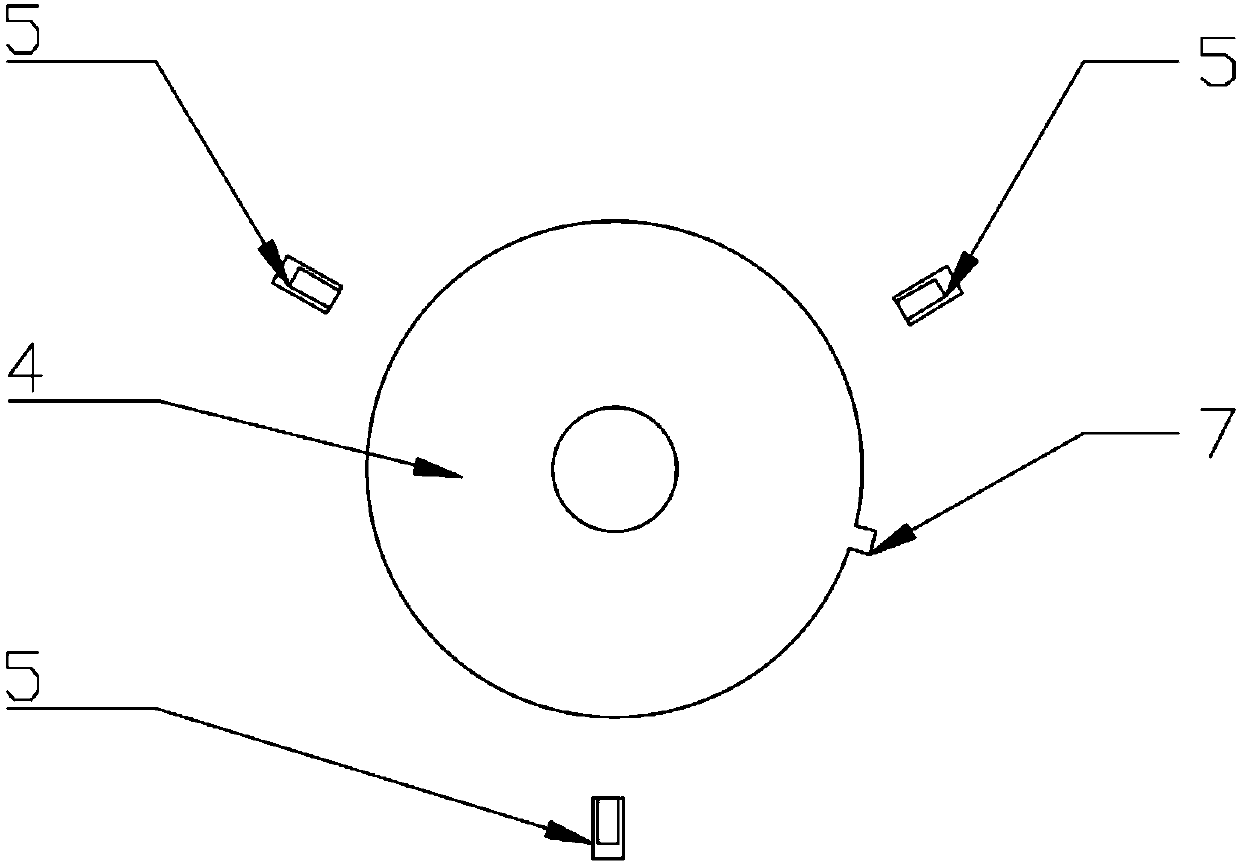
[0052] Such as Figure 1 to Figure 3 As shown, a visual sensor system for detection of dry battery pulp paper winding defects includes a visual sensor 1, a ring light source 2, a bracket 3, a turntable 4, and several synchronous trigger sensors 5, and the dry battery 6 to be detected is placed on the turntable 4 center, the turntable 4 keeps rotating around the central axis at a constant speed, and several synchronous trigger sensors 5 are evenly distributed on the side of the turntable 4 at equal intervals.

[0053] In this embodiment, the number of synchronous trigger sensors is 3, and the 3 synchronous trigger sensors 5 are evenly distributed on the side of the turntable 4 at intervals of 120 degrees. Similarly, four synchronous trigger sensors can also be used, and the four synchronous trigger sensors 5 are evenly distributed on the side of the turntable 4 at intervals of 90 degrees. The above-mentioned number of synchronous trigger sensors does not constitute a limitatio...

Embodiment 2

[0063] This embodiment is based on a visual sensor system for detection of winding defects of dry battery pulp paper disclosed in the above embodiments, and provides a method for detection of winding defects of dry battery pulp paper, as shown in Figure 4 As shown, the method for detecting the winding defects of dry battery pulp paper provided in this embodiment includes steps:

[0064] S1. The visual sensor 1 is initialized, and the synchronous trigger module, the light source driver module, the image processing module, etc. are sequentially set to default values;

[0065] S2. The visual sensor 1 loops to judge whether several synchronous trigger sensors 5 have generated switch signals, if any synchronous trigger sensor 5 has been triggered, go to the next step, otherwise continue to wait for the switch signal;

[0066] S3. The synchronous trigger module of the visual sensor 1 processes the position information obtained by the synchronous trigger sensor 5, generates a light ...


PUM


Abstract

The invention discloses a visual sensor system used for dry cell slurry layer paper winding defect detection and a method thereof. The system comprises a visual sensor, a ring light source, a support,a rotating disk, and three synchronous triggering sensors, a to-be-detected dry cell is placed at center of a rotating disk, the rotating disk keeps rotation at a uniform speed by winding central axis, three synchronous triggering sensors are uniformly distributed at a side surface of the rotating disk at intervals according to 120 DEG, the ring light source is placed at a front end of the visualsensor, the visual sensor is arranged at the support, axis at end of the support and a vertical direction form a fixed included angle, and its extending line and the axis of the dry cell are intersected at the top of the dry cell, and the visual sensor is connected with the synchronous triggering sensors and the ring light source, so that high speed synchronization problem of dry cell positioning, light source control and image acquisition can be solved. The visual sensor system solves the problem that whether visual inspection of the dry cell by eyes has slurry layer paper winding defect ornot, and has the advantages of full automation, fast detection speed, and high system reliability.

Description

technical field [0001] The invention relates to the technical field of visual sensors, in particular to a visual sensor system and method for detecting winding defects of dry battery pulp paper. Background technique [0002] In the dry battery production process, due to its cumbersome process and complicated process, defects in carbon rods, sealing glue, bottom bowl paper, carbon rods, pulp layer paper, etc. are prone to occur. Among them, the pulp paper is the separator paper located inside the zinc cylinder of the dry battery, which needs to be inserted into the zinc cylinder after winding, so the space where it is located is deep and narrow, and once there is a defect in the winding of the pulp paper, it is extremely difficult It is easy to cause problems such as liquid leakage and chronic short circuit in the subsequent use of dry batteries. If the image is collected at a fixed position outside the zinc cylinder, due to the limitation of the shooting angle, only the ima...

Claims


Application Information

Patent Timeline
IPC IPC(8): G01N21/88
CPCG01N21/8851G01N2021/8887
Inventor 叶峰洪峥赖乙宗苏凌丰
Owner SOUTH CHINA UNIV OF TECH
Why Eureka
Try Eureka