An access control system, an access control robot and an operating method of the system

An operation method and robot system technology, applied in the direction of instruments, time registers, single input port/output port registers, etc., can solve the problems of high cost, low security, fraudulent access control system credit, etc., to prevent theft Brushing or proxy brushing, the effect of improving security

Active Publication Date: 2018-05-15
BEIJING UNISROBO TECH CO LTD
7 Cites 2 Cited by

AI-Extracted Technical Summary

Problems solved by technology

During the process of entering passwords, if the authorized or authenticated personnel do not pay attention to actively cover the input keypad, or malicious intruders install sneak shooting equipment in advance, the passwords entered by visitors are easily stolen and leaked
Fingerprint identification technology can improve the security of the access control system to a certain extent by collecting and comparing single or multiple fingerprints of visitors. However, malicious intruders or attendance checkers can still use resin to reverse the fingerprints of authorized and authenticated users. Obtain the fingerprint film of the user through the model to defraud the credit of the access control system
[0004] Another access control system can judge the identity of the vis...

Method used

According to the access control robot and its operating method of the present invention, using the user's input habits, the fingerprints spanning different keypads on the input panel are combined according to the area and input sequence to obtain a composite password, which can effectively prevent fraudulent brushing or Brush on behalf of, thereby improving security.
[0039] Specifically, for the input panel 6 shown in FIG. 1, it includes a glass or plastic substrate 6a at the bottom, a transparent flexible cover plate 6c of plastic or resin material at the top, and between the substrate 6a and the cover plate 6c. A plurality of spacers 6b formed of opaque/light-absorbing materials such as black resin (used to provide support between the substrate and the cover plate, and at the same time prevent the photoelectric sensor from being interfered by the adjacent keypad). The spacer divides the input panel into a plurality of button areas, such as English letters or symbols on the standard keyboard shown in Figure 2b, that is, the bottom of the blank part outside the box shown in Figure 2b corresponds to the spacer 6b, and the box The inner letter or character part corresponds to the keypad space surrounded by the spacer 6b, the base plate 6a, and the cover plate 6c. Each keypad contains a password detection unit composed of a matrix/row and column of piezoelectric sensors 6d, and a fingerprint detection unit composed of a matrix of photoelectric sensors 6e (preferably integrated with unshown LEDs or lasers to improve fingerprint detection accuracy) unit. For the convenience of i...

Abstract

An operating method of an access control robot system is disclosed. The method includes detecting a fact that fingers of a user are pressed one or more press button zones on an input panel; measuringand recording the area pressed by the fingers of the user in each press button zone; measuring and recording partial fingerprints of user's fingers in each press button zone; for each press button zone, forming a fingerprint code of each press button zone by combining the measured partial fingerprint and the area pressed by the corresponding user's finger; connecting the fingerprint codes in the press button zones in series to form a total fingerprint code for one time of pressing; and connecting the total fingerprint code in each time of pressing to form a password of the access control system. According to the access control robot and the operating method thereof, the compound password is obtained by combining fingerprints in different button zones on the input panel according to areas and input sequences by utilizing an input habit of the user, and unauthorized or acting access card brushing can be efficiently prevented, thus improving safety.

Application Domain

Individual entry/exit registers

Technology Topic

Robotic systemsFingerprint +4

Image

  • An access control system, an access control robot and an operating method of the system
  • An access control system, an access control robot and an operating method of the system
  • An access control system, an access control robot and an operating method of the system

Examples

  • Experimental program(1)

Example Embodiment

[0036] The features and technical effects of the technical solution of the present invention will be described in detail below with reference to the drawings and in conjunction with exemplary embodiments, and an access control system, robot and operation method thereof that can efficiently prevent theft or replacement of brushes and improve security are disclosed. It should be pointed out that similar reference signs indicate similar structures. The terms "first", "second", "upper", "lower", etc. used in this application can be used to modify various system components or method steps. . Unless otherwise specified, these modifications do not imply the spatial, order, or hierarchical relationship of the modified system components or method steps.
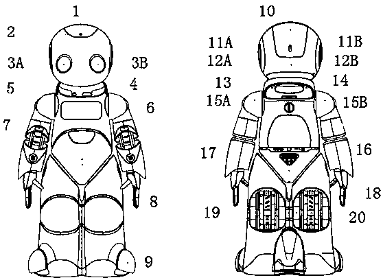
[0037] Such as figure 1 As shown, the access control robot according to the embodiment of the present invention includes: a high-sensitivity microphone 1 located on top of the head, used to collect or receive surrounding sound information or voice information of persons; a high-definition camera 2 located on the forehead, used to collect or receive faces of persons Topological structure information (such as bone outline); expression sensors 3A and 3B located in the eyes, used to capture the facial details of the person (such as the dynamic changes of the iris, retina, eyebrows or corners of the eyes, the smile reflected by the lips or teeth, ears or The slight twitch of the tip of the nose) to reflect the biological information or emotional information of the person; touch sensors located in various parts of the robot, including the chin touch sensor 4, abdomen touch sensor 7, overhead touch sensor 10, left/right ear touch sensor 12A/12B, and back of the brain Touch sensor 13, left shoulder/right shoulder touch sensor 15A/15B, buttocks touch sensor 17, these touch sensors are used to recognize the tactile interaction with the user, thereby improving the accuracy of user identity or emotion recognition, and provide physical contact with the user The stress information is used to feed back and modify the movement/rotation parameters of the robot body; the 3D depth camera 5 located on the neck of the neck is used to collect the depth information of the surrounding scene; the input panel 6 located on the chest is used to display the virtual keypad (such as Figure 2b (Shown) and use the built-in photoelectric sensor under the panel to scan to obtain the fingerprint or part of the fingerprint in each key area; the 2D lidar 8 located in the lower abdomen is used to measure the distance between the user or other moving objects in the scene and the robot to assist in determining the object The height, moving speed, limb static/walking posture, etc.; the omni-directional moving wheel 9 at the foot is used to drive the entire robot to move along the path selected by pre-stored or real-time judgment; the speaker 11A/11B at the ear is used to The user transmits voice and audio information; the emergency stop switch 14 on the back is used to stop the movement or actions of the robot in an emergency to improve safety; the power button 16 on the back waist is used to manually start the operating system of the access control robot to provide Reception and consultation services; the hand biosensor 18 located on the hand is used to collect the user’s fingerprint, measure the user’s skin moisture content (resistivity) or roughness, measure the stress of shaking hands with the user, and measure the user’s pulse or capillary Oxygen content, etc.; the charging port 19 on the side of the leg, and the power switch on the back of the leg.
[0038] Figure 2a Showing a cross-sectional view of an input panel of an access control robot according to an embodiment of the present invention, Figure 2b A schematic diagram of a password input interface of an access control robot according to an embodiment of the present invention is shown.
[0039] Specifically, for figure 1 The input panel 6 shown includes a glass or plastic substrate 6a on the bottom, a transparent flexible cover 6c of plastic or resin material on the top, and an opaque/light-absorbing material such as black resin between the substrate 6a and the cover 6c. Multiple spacers 6b (used to provide support between the base plate and the cover plate, and at the same time prevent the photoelectric sensor from being interfered by the adjacent button area). The spacer divides the input panel into multiple key areas, for example Figure 2b English letters or symbols on the standard keyboard shown, that is Figure 2b The blank part outside the box shown below corresponds to the spacer 6b, and the letter or character part inside the box corresponds to the key area space enclosed by the spacer 6b, the base 6a, and the cover 6c. Each key zone contains a password detection unit composed of a matrix/column of piezoelectric sensors 6d, and a fingerprint detection unit composed of a matrix of photoelectric sensors 6e (preferably integrated with LEDs or lasers not shown to improve fingerprint detection accuracy) unit. For convenience, Figure 2a Each button area only shows a group of 6d/6e. In fact, each button area contains N×N pixels. N is a natural number greater than 1, for example, 128×128, 256×256 pixels, each pixel At least one photoelectric sensor 6e is included to improve fingerprint detection accuracy, and every N pixels (for example, a column or a row, or a block surrounded by N pixels) includes at least one piezoelectric sensor 6d to balance character detection accuracy and cost. In addition, each pixel also includes an OLED and its driving circuit (not shown) for displaying virtual keys. The matrix of the piezoelectric sensor 6d can use a person's finger to press the key area to cause a change in the distance between the capacitor plates to detect that a certain key is pressed and output a corresponding character. The matrix of the photoelectric sensor 6e can use the unevenness of the fingerprint to cause the reflected light (reflected ambient light, or the light reflected by the LED or laser to actively emit light) to measure the user's fingerprint or partial fingerprint. Within each pixel, a dam (not shown) made of transparent resin may be included between the piezoelectric sensor 6d, the photoelectric sensor 6e and the OLED/drive circuit to provide mechanical support. Preferably, the bottom or top of the spacer 6b further includes a piezoelectric sensor (not shown) to measure the pressure of the spacer 6b. Other structures of the input panel such as interlayer insulation layer, passivation layer, metal interconnection line, power supply, etc. Figure 2a Not shown in.
[0040] Such as Figure 2b Shown in figure 1 A virtual standard keyboard is displayed on the input panel 6 of the access control robot, including multiple letters, numbers, and symbols. The dashed ellipse represents the range and sequence of finger pressing when the user enters the password. The dashed ellipse No. 1 represents the intersection of the three letters J, U, and I first, and the dashed ellipse No. 2 represents the user pressed R and F. In the intersection area of ​​the letters, the dashed ellipse No. 3 represents that the user continues to press the letter Y... (the subsequent password input process is not shown). By designing the size of the key area of ​​the virtual keyboard, such as increasing the size of the blank area between the key areas, that is, the size of the spacer 6b, a single finger of the user can press at most three adjacent key areas at the same time, and a single fingerprint There is a difference in the distribution area between adjacent key areas. For example, for the first press, the letter J occupies the largest area, the letter U occupies the center, and the letter I occupies the smallest area. For the second press, the letter R occupies a larger area, and the letter F occupies a smaller area. For the third press, the fingerprints are mainly distributed in the range of the letter Y, and the rest are located on the spacer 6b.
[0041] Thus, the input panel 6 adopts Figure 4 The operation method of the access control robot shown is to detect, compile and synthesize the user password, such as image 3 The structure diagram of the password field of the access control robot is shown in the figure.
[0042] First, it is detected that the user's finger presses one or more key areas at the same time. The detection unit composed of the piezoelectric sensor 6d in each key area measures whether there is a pressure change in the key area, that is, whether the capacitance change caused by the change in the distance between the capacitor plates caused by the finger press exceeds the preset threshold, and if it exceeds the threshold It is determined that there is a finger press in the key area. E.g image 3 As shown in the upper part, it is detected for the first time that the user's finger presses the three key areas J, U, I at the same time; as shown in the middle part, it is detected that the user's finger presses the two key areas R and F at the same time for the second time; It is detected three times that the user has only pressed Y.
[0043] Second, measure and record the area of ​​each button area pressed by the user's finger. As mentioned above, the piezoelectric sensors 6d in the N×N pixels in a single button area form a matrix of rows and columns, where m piezoelectric sensors are located under the user's finger and cause a capacitance change exceeding the threshold. You can use m/N 2 To represent the area ratio of the finger in the button area. For the first key press, the letter J corresponds to m 1 , The letter U corresponds to m 2 , The letter I corresponds to m 3 , And m 1 m 2 m 3. By analogy, the size of the button area each time the user's finger presses is sorted, for example, the second time R corresponding to m1 is greater than F corresponding to m2, and so on.
[0044] Then, detect and record part of the fingerprints of the user's finger in each key area. As described above, a matrix of photoelectric sensors 6e in each key zone is used to measure the user's fingerprint. Specifically, for N×N pixels in each key area, a single photoelectric sensor 6e in each pixel receives ambient light or LED or laser light emitted by the fingerprint concave-convex surface and is reflected by the reference light intensity and the reflected light intensity ( Determined according to the sensor current) to reflect the degree of unevenness of the fingerprint, for example, with [0,2 k -1] (k is a positive integer, for example, k is 2-8), that is, the k-bit binary code represents the degree of unevenness of the fingerprint in a single pixel, that is, the grayscale. The fingerprint information collected on each pixel in the key area, that is, the gray scale, is stored in the memory.
[0045] Subsequently, for each key area, the fingerprint code of each key area is formed according to the combination of the detected part of the fingerprint and the area pressed by the finger. Specifically, for each key area scanned line by line, m i Fingerprint gray scale (each is k-bit binary code), using Golomb-Rice compression code, the area of ​​each key area is m i (Or its normalized value) is the coding parameter, and the fingerprint codes of the first, second, and third key zones are obtained in sequence. In addition, other compression algorithms can also be used, such as JPEG-LS with the area normalization value as the quality factor, JBIG, RLE, etc. with the area normalization factor as the parameter.
[0046] Then, the fingerprint codes of each key zone are concatenated to form a total fingerprint code of a single press, and preferably the remaining insufficient part is filled with bit-filling codes. For example, the complement codes are all 0 or all 1, or the ratio of the average pressing pressure to the preset reference value measured by the piezoelectric sensor on the top or bottom of the adjacent spacer 6b to further reflect the pressing force, or to store the area of ​​each key area m i The normalized value of.
[0047] Finally, the total fingerprint code obtained by pressing multiple times is concatenated to form the final password and stored in the memory of the access control system.
[0048] The password entered by the user is compared with the password pre-stored in the system section by section. For the fingerprint code and complement code of each key zone, the input password is determined to be correct only when the difference is less than a predetermined threshold (for example, 5% or 8%). The user is an authorized or trusted user.
[0049] In this way, the user does not need to perform any concealment actions when entering the password, and only by habitual actions for blind typing can obtain a unique password closely related to the user's fingerprint, tapping position, and tapping strength as credentials for identity verification, which greatly improves Improve the security of the access control system. Even if an unauthorized user such as an intruder or a third party obtains the user’s fingerprint, they do not know the distribution of the user’s tapping area (that is, Figure 2b Mid-span keypad position and area size) and strength ( Figure 2a Under the premise that the pressure measured by the piezoelectric sensor on the upper or lower middle spacer 6b), it cannot be stolen or replaced. The security of the access control system is improved. At the same time, the cost is compared with the access control system using other physiological parameters such as retina and DNA. Large-scale reduction. Furthermore, since there are no restrictions on the area and sequence of user input, the friendliness and ease of use of the access control system are also greatly improved, which is conducive to the promotion and large-scale application of the access control system.
[0050] According to the access control robot and its operation method of the present invention, the user’s input habits are used to combine fingerprints across different keypads on the input panel in accordance with the area and input sequence to obtain a composite password, which can effectively prevent theft or brushing. Thereby improving safety.
[0051] Although the present invention has been described with reference to one or more exemplary embodiments, those skilled in the art can know that various suitable changes and equivalent manners can be made to the system and method without departing from the scope of the present invention. In addition, many modifications that may be suitable for specific situations or materials can be made from the disclosed teachings without departing from the scope of the present invention. Therefore, the purpose of the present invention is not limited to the specific embodiment disclosed as the best embodiment for realizing the present invention, but the disclosed system and method will include all embodiments falling within the scope of the present invention.

PUM

no PUM

Description & Claims & Application Information

We can also present the details of the Description, Claims and Application information to help users get a comprehensive understanding of the technical details of the patent, such as background art, summary of invention, brief description of drawings, description of embodiments, and other original content. On the other hand, users can also determine the specific scope of protection of the technology through the list of claims; as well as understand the changes in the life cycle of the technology with the presentation of the patent timeline. Login to view more.

Similar technology patents

Trusted computing platform chip applicable to mobile communication equipment and authentication method thereof

InactiveCN101986641Aimprove securityachieve security
Owner:HANGZHOU SYNOCHIP DATA SECURITY TECH CO LTD

Hidden frame glass curtain wall structure and method for mounting same

InactiveCN107829513AImprove decorationimprove security
Owner:XINCHANG SICHUANG DESIGN CONSULTING CO LTD

Classification and recommendation of technical efficacy words

  • improve security

Pesticide micro-capsule granules and preparation method thereof

InactiveCN102100229Alow toxicityimprove security
Owner:联合国南通农药剂型开发中心 +1

Method for achieving user authentication by utilizing camera

InactiveCN103678984Aimprove securityGuaranteed picture quality
Owner:湖北微模式科技发展有限公司
Why Eureka
Try Eureka