
Mounting and fixing structure of an independently packaged radio frequency power amplifier chip

A power amplification chip and fixed structure technology, applied to the circuit layout on the support structure, printed circuit connected with non-printed electrical components, printed circuit, etc., can solve problems such as poor grounding, power amplifier module failure, and large amplitude. Achieve the effect of improving grounding performance and ensuring grounding performance

Active Publication Date: 2020-08-11
THE 41ST INST OF CHINA ELECTRONICS TECH GRP
View PDF5 Cites 0 Cited by
  • Summary
  • Abstract
  • Description
  • Claims
  • Application Information

AI Technical Summary

Problems solved by technology

This will lead to poor grounding at the center of the bottom of the chip, which will easily generate parasitic resistance, capacitance, and reactance, which will affect the performance of the chip
At the same time, poor contact causes the contact thermal resistance between the chip and the cavity to increase, which affects the heat dissipation of the chip and further affects the performance of the chip
In addition, because only the flanges on both sides of the chip are fixed, in the shock and vibration test, the vibration amplitude at the middle position is large, which may easily lead to cracking of the chip pins and the printed board, or even breakage of the lead chip pins, resulting in failure of the power amplifier module
[0006] For the non-flange power amplifier chip, it is fixed by welding or bonding, the chip assembly process is complicated, and it is inconvenient to disassemble and assemble, and the maintainability is low

Method used


Image

  • Mounting and fixing structure of an independently packaged radio frequency power amplifier chip
  • Mounting and fixing structure of an independently packaged radio frequency power amplifier chip
  • Mounting and fixing structure of an independently packaged radio frequency power amplifier chip

Examples


Embodiment Construction

[0032] The following will clearly and completely describe the technical solutions in the embodiments of the present invention with reference to the accompanying drawings in the embodiments of the present invention. Obviously, the described embodiments are only some, not all, embodiments of the present invention. Based on the embodiments of the present invention, all other embodiments obtained by persons of ordinary skill in the art without making creative efforts belong to the protection scope of the present invention.

[0033] By adopting the installation and fixing structure of the independently packaged power amplifier chip of the present invention, the grounding performance, heat dissipation performance and impact resistance and vibration resistance performance of the flange type power amplifier chip can be improved; While improving the vibration performance, it can reduce the assembly difficulty of the power amplifier chip and improve the maintainability of the amplifier. ...


PUM


Abstract

The invention proposes an independently packaged power amplification chip installation and fixing structure, which mainly includes: a support seat, an adjustment piece, a large flat head adjustment top wire, and a small flat head adjustment top wire; the support seat is an inverted "concave" structure, and the power amplifier The chips, adjusting pieces, adjusting jackscrews and fastening screws are all contained in the support seat after installation; Tighten alternately. The mounting and fixing structure of the present invention has strong applicability, and can be applied to installing and fixing flange-type power amplifier chips, and can also be used for installing and fixing non-flange-type power amplifier chips; for flange-type power amplifier chips, its grounding performance, heat dissipation performance and anti-corrosion performance can be improved. Shock vibration performance; for non-flange power amplifier chips, while ensuring grounding performance, heat dissipation performance, and shock and vibration resistance performance, it can reduce the difficulty of assembling the power amplifier chip and improve the maintainability of the amplifier.

Description

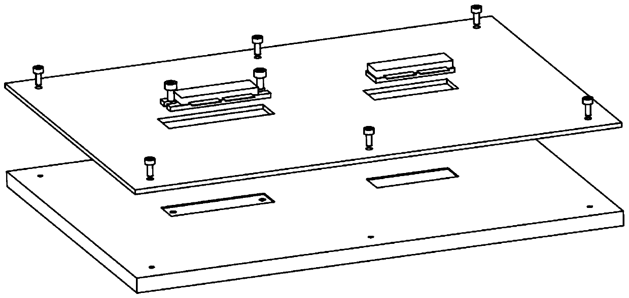
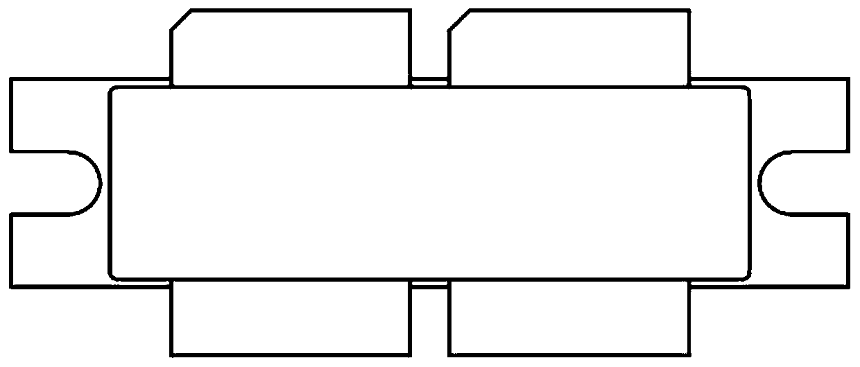
technical field [0001] The invention relates to the field of power amplifiers, in particular to a mounting and fixing structure for an independently packaged radio frequency power amplifier chip. Background technique [0002] The installation structure of the traditional independently packaged RF power amplifier chip (hereinafter referred to as the power amplifier chip or chip) is as follows: figure 1 , figure 2 shown. The printed board is slotted, the chip passes through the slot, the chip pins are welded to the pads of the printed board, and the printed board is fixed on the cavity board by screws. The back of the power amplifier chip is the ground terminal, which needs to be in good contact with the cavity. The flange type power amplifier chip is usually fixed on the cavity plate by screws; the non-flange type power amplifier chip is usually welded or bonded to the cavity plate. [0003] The RF power amplifier chip is the core device in the high-power amplifier. Acco...

Claims


Application Information

Patent Timeline
Patent Type & Authority Patents(China)
IPC IPC(8): H05K7/02H05K1/18
CPCH05K1/18H05K7/02H05K2201/10598
Inventor 王加路吴强赵树伟张文兴马建壮曲志明朴智棋邴宇涵
Owner THE 41ST INST OF CHINA ELECTRONICS TECH GRP
Learn More