Water pipe cutting equipment for hydraulic engineering
A technology of cutting equipment and water conservancy engineering, which is applied in the direction of metal processing equipment, shearing equipment, pipe shearing device, etc., can solve the problems of low cutting efficiency, slow cutting speed, and irritating odor, and achieve high cutting efficiency, fast effect
- Summary
- Abstract
- Description
- Claims
- Application Information
AI Technical Summary
Problems solved by technology
Method used
Image

Examples
Embodiment 1
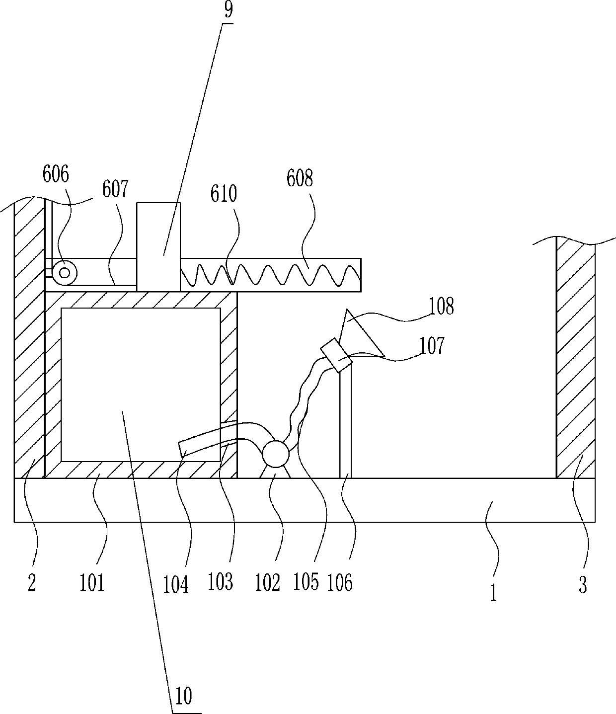
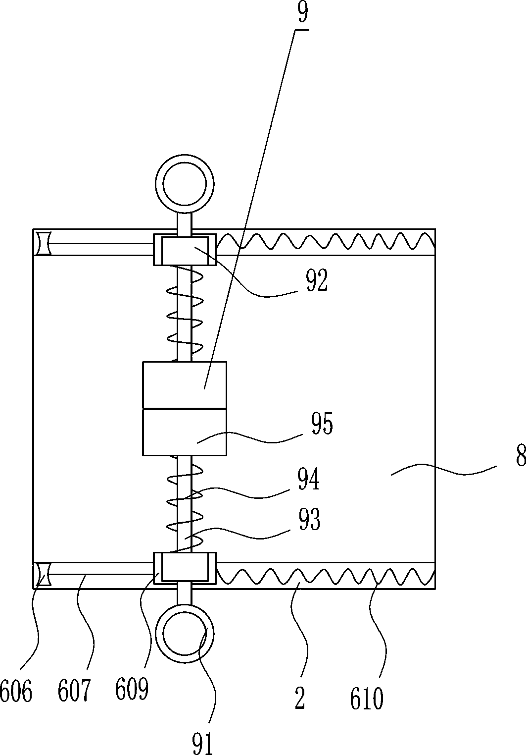
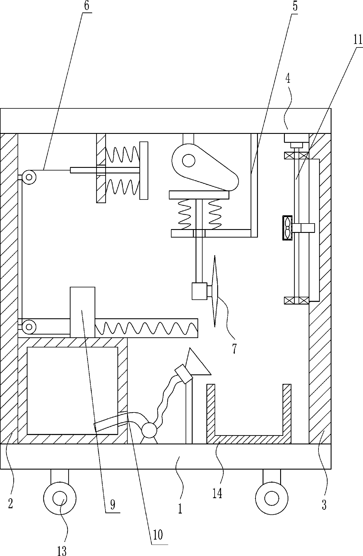
[0038] A water pipe cutting equipment for water conservancy projects, such as Figure 1-7 As shown, it includes a base plate 1, a left support plate 2, a right support plate 3, a fixed rod 4, a driving mechanism 5, a pushing mechanism 6, a clamping mechanism 9, a cutting blade 7 and a horizontal plate 8, and the left side of the base plate 1 is provided with There is a left support plate 2, a right support plate 3 is arranged on the right side of the top of the bottom plate 1, a fixed rod 4 is connected between the top of the left support plate 2 and the top of the right support plate 3, and a drive is provided on the right side of the bottom of the fixed rod 4. Mechanism 5, the bottom end of driving mechanism 5 is connected with cutting blade 7, the left side of fixed rod 4 bottom is provided with pushing mechanism 6, the right side of left support plate 2 is provided with horizontal plate 8, and the top of horizontal plate 8 is provided with Clamping mechanism 9 , parts of w...
Embodiment 2
[0040] A water pipe cutting equipment for water conservancy projects, such as Figure 1-7 As shown, it includes a base plate 1, a left support plate 2, a right support plate 3, a fixed rod 4, a driving mechanism 5, a pushing mechanism 6, a clamping mechanism 9, a cutting blade 7 and a horizontal plate 8, and the left side of the base plate 1 is provided with There is a left support plate 2, a right support plate 3 is arranged on the right side of the top of the bottom plate 1, a fixed rod 4 is connected between the top of the left support plate 2 and the top of the right support plate 3, and a drive is provided on the right side of the bottom of the fixed rod 4. Mechanism 5, the bottom end of driving mechanism 5 is connected with cutting blade 7, the left side of fixed rod 4 bottom is provided with pushing mechanism 6, the right side of left support plate 2 is provided with horizontal plate 8, and the top of horizontal plate 8 is provided with Clamping mechanism 9 , parts of w...
Embodiment 3
[0043] A water pipe cutting equipment for water conservancy projects, such as Figure 1-7 As shown, it includes a base plate 1, a left support plate 2, a right support plate 3, a fixed rod 4, a driving mechanism 5, a pushing mechanism 6, a clamping mechanism 9, a cutting blade 7 and a horizontal plate 8, and the left side of the base plate 1 is provided with There is a left support plate 2, a right support plate 3 is arranged on the right side of the top of the bottom plate 1, a fixed rod 4 is connected between the top of the left support plate 2 and the top of the right support plate 3, and a drive is provided on the right side of the bottom of the fixed rod 4. Mechanism 5, the bottom end of driving mechanism 5 is connected with cutting blade 7, the left side of fixed rod 4 bottom is provided with pushing mechanism 6, the right side of left support plate 2 is provided with horizontal plate 8, and the top of horizontal plate 8 is provided with Clamping mechanism 9 , parts of w...
PUM
 Abstract
Description
Claims
Application Information
 - Generate Ideas
- Intellectual Property
- Life Sciences
- Materials
- Tech Scout
- Unparalleled Data Quality
- Higher Quality Content
- 60% Fewer Hallucinations
Browse by: Latest US Patents, China's latest patents, Technical Efficacy Thesaurus, Application Domain, Technology Topic, Popular Technical Reports.
© 2025 PatSnap. All rights reserved.Legal|Privacy policy|Modern Slavery Act Transparency Statement|Sitemap|About US| Contact US: help@patsnap.com