Hydraulic lifting device of loading and unloading trolley

A technology of hydraulic lifting devices and loading and unloading vehicles, which is applied in the direction of lifting devices, lifting frames, and vehicles with inclined load-carrying movements, etc., which can solve the cost of not being able to save fuel and electricity, waste of material and labor costs, and inconvenient use of loading and unloading vehicles and other issues, to achieve the effects of increasing maneuverability and flexibility, reducing fuel consumption costs, and reducing operating costs

Inactive Publication Date: 2018-05-18
朱宗华
View PDF7 Cites 0 Cited by
  • Summary
  • Abstract
  • Description
  • Claims
  • Application Information

AI Technical Summary

Problems solved by technology

Even so, there are still certain deficiencies and defects in the equipment on the market now. The field of loading and unloading trucks with hydraulic lifting devices is relatively lacking in the market now, which makes the loading and unloading trucks inconvenient in use and cannot save oil. Secondly, the use effect is not good, so that the loading and unloading truck cannot achieve the purpose of convenience in the process of using the loaded goods and unloading the goods, which brings certain troubles to the workers' operation and wastes material resources and manpower costs.

Method used


Image

  • Hydraulic lifting device of loading and unloading trolley
  • Hydraulic lifting device of loading and unloading trolley
  • Hydraulic lifting device of loading and unloading trolley

Examples


Embodiment Construction

[0016] The following will clearly and completely describe the technical solutions in the embodiments of the present invention with reference to the accompanying drawings in the embodiments of the present invention. Obviously, the described embodiments are only some, not all, embodiments of the present invention. Based on the embodiments of the present invention, all other embodiments obtained by persons of ordinary skill in the art without making creative efforts belong to the protection scope of the present invention.

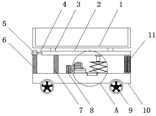
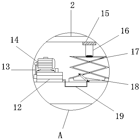
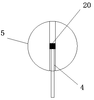
[0017] see Figure 1-3 , an embodiment provided by the present invention: a hydraulic lifting device for loading and unloading trucks, including a car bucket 1; a steel pipe slide rail 2 is provided below the car bucket 1 through a load-bearing pad 3, and the steel pipe slide rail 2 and the slider 15 below are closely connected Cooperate to make the lifting process of one end of the car body easier and reduce fuel consumption. One end of the steel pipe slide r...


PUM


Abstract

The invention discloses a hydraulic lifting device of a loading and unloading trolley. The hydraulic lifting device of the loading and unloading trolley includes a trolley hopper. The lower portion ofthe trolley hopper is provided with a steel pipe sliding rail through a bearing pad. One end of the steel pipe sliding rail is fixedly connected with a shaft pipe. The steel pipe sliding rail is connected with a round shaft through the shaft pipe at one end. The lower portion of the round shaft is fixedly provided with a supporting pipe and the round shaft is fixed to the upper end of the supporting pipe. The lower end of the supporting pipe is fixedly connected with a trolley plate. The upper side of the trolley plate is provided with a spring column and the lower portion of the spring column is fixed to the upper wall of the trolley plate in clamped and connecting modes. According to the hydraulic lifting device of the loading and unloading trolley, a principle of hydraulic lifting is used to construct the loading and unloading trolley, the loading and unloading trolley is internally provided with the steel pipe sliding rail and a sliding block column through the hydraulic lifting device; in the using process, the hydraulic device drives the sliding block column to rise; and one end of the trolley hopper rises under the effects of the sliding block column and the steel pipe sliding rail. According to the hydraulic lifting device of the loading and unloading trolley, one end of the trolley hopper can rise and lower automatically; the process of loading and unloading is made to be flexible and convenient; and maneuverability and flexibility of the loading and unloading trolley are improved.

Description

technical field [0001] The invention relates to the technical field of mechanical equipment, in particular to a hydraulic lifting device for loading and unloading vehicles. Background technique [0002] At present, the loading and unloading truck is the logistics handling equipment that plays the role of moving goods. When the loading and unloading truck is used at the handling station, it holds up the goods it carries, and the hydraulic system is driven by manpower to realize the lifting and lowering of the pallet goods, and the manpower is pulled to complete the handling operation. It is the easiest, most effective and most common loading and unloading and handling tool in the pallet transport tool of the handling station. In real life, there are many applications of loading and unloading trucks, most of which are used in commercial logistics, generally used for truck drivers to pull goods or clean up municipal garbage, and have been widely used in life, greatly improving...

Claims


Application Information

Patent Timeline
Patent Type & Authority Applications(China)
IPC IPC(8): B60P1/16B66F7/08B66F7/06B66F7/28
Inventor 朱宗华
Owner 朱宗华
Why Eureka
Try Eureka