Controllable passive stabilization water tank

An anti-rolling water tank and passive technology, applied in the field of ship components, can solve the problems of increased ship roll, frequent opening and closing, and increased space occupation, so as to reduce the probability of ship roll, maintain consistency, and increase safety sexual effect

Pending Publication Date: 2018-05-18
WUXI HAIHE EQUIP TECH CO LTD
View PDF1 Cites 4 Cited by
  • Summary
  • Abstract
  • Description
  • Claims
  • Application Information

AI Technical Summary

Problems solved by technology

However, when the air butterfly valve 2 is used to adjust the water flow oscillation cycle of the anti-rolling tank, it needs to be opened and closed frequently, which consumes a lot of energy, is easy to be damaged, and has a short service life.
Moreover, when the anti-rolling water tank is not working, the air butterfly valve 2 is closed. At this time, if the liquid levels of the left and right wing tanks 1 are inconsistent, it will increase the ship's roll and affect the safety of the ship's navigation.
If the air b

Method used


Image

  • Controllable passive stabilization water tank
  • Controllable passive stabilization water tank

Examples


Embodiment Construction

[0015] The present invention will be described in further detail below in conjunction with the accompanying drawings.

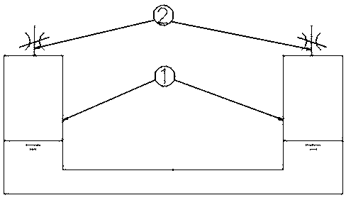
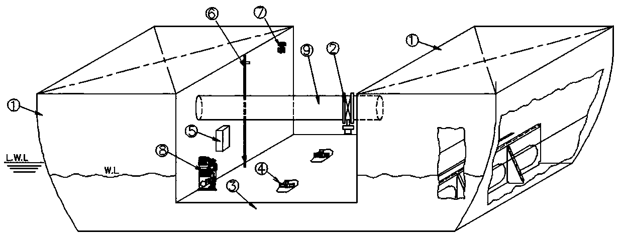
[0016] Such as figure 2 As shown, the controllable passive anti-rolling water tank of the present invention includes a U-shaped cabin, the cabins on the left and right sides of the U-shaped are wing cabins 1, and the cabin between the two wing cabins is the lower cabin 3, and there is damping in the lower cabin 3 Baffle 4. The cabin is connected with a control box 5, and there are liquid level sensors 6 in the two wing cabins 1, and there are pressure relief valves 7 on the two wing cabins 1, and the liquid level sensors 6 and the pressure relief valve 7 are connected to the control box 5 are electrically connected.

[0017] The pressure relief valves 7 are all arranged on the upper parts of the opposite surfaces of the two wing compartments 1 .

[0018] The upper parts of the two wing compartments 1 are communicated through a pipeline 9, and an air butte...


PUM


Abstract

The invention relates to a naval vessel part, in particular to an adjustable passive stabilization water tank. The adjustable passive stabilization water tank includes U-shaped cabins, the left and right sides of the U-shaped cabins are wing tanks, a cabin between the two wing tanks is a lower cabin, and damping blocking plates are arranged in the lower cabin. The adjustable passive stabilizationwater tank is characterized in that control boxes are connected on the cabins, liquid level sensors are arranged in the two wing cabins, decompression valves are arranged on the two wing cabins, and the liquid level sensors and the decompression valves are both electrically connected with the control boxes. The adjustable passive stabilization water tank is low in energy consumption and long in service life, and the uniformity of the liquid level height of the left and right wing cabins can be maintained, and the safety of vessels during sailing can be improved.

Description

technical field [0001] The invention relates to a ship component, in particular to a controllable passive anti-rolling water tank. Background technique [0002] Chinese patent ZL200820150739.0 relates to an anti-rolling water tank control device, such as figure 1 As shown, air butterfly valves 2 are respectively installed on the tops of the left and right wing tanks 1 of the U-shaped anti-rolling water tank, directly connected to the external atmosphere, and the flow of liquid in the cabin is adjusted by opening and closing the air butterfly valves 2, so as to match the ship's roll to achieve the purpose of reducing ship roll. However, when the air butterfly valve 2 is used to adjust the water flow oscillation period of the anti-rolling water tank, it needs to be opened and closed frequently, which consumes a lot of energy, is easy to be damaged, and has a short service life. Moreover, when the anti-rolling water tank is not working, the air butterfly valve 2 is closed. At...

Claims


Application Information

Patent Timeline
IPC IPC(8): B63B39/03
CPCB63B39/03
Inventor 盛洁单新华何晓燕段金刚陈宏
Owner WUXI HAIHE EQUIP TECH CO LTD
Why Eureka
Try Eureka