Lifting appliance for crane maintenance

A technology of cranes and spreaders, which is applied in the directions of load hanging components, transportation and packaging, and can solve problems such as large wear and tear of fixtures.

Active Publication Date: 2018-05-18
徐州天骋智能科技有限公司
View PDF4 Cites 2 Cited by
  • Summary
  • Abstract
  • Description
  • Claims
  • Application Information

AI Technical Summary

Problems solved by technology

[0005] The invention discloses a crane maintenance sling, which aims to solve the problem that the sling in the prior art is in direct contact with the ground resulting in large wear and tear of the fixture

Method used


Image

  • Lifting appliance for crane maintenance

Examples


Embodiment Construction

[0019] The following is further described in detail through specific implementation methods:

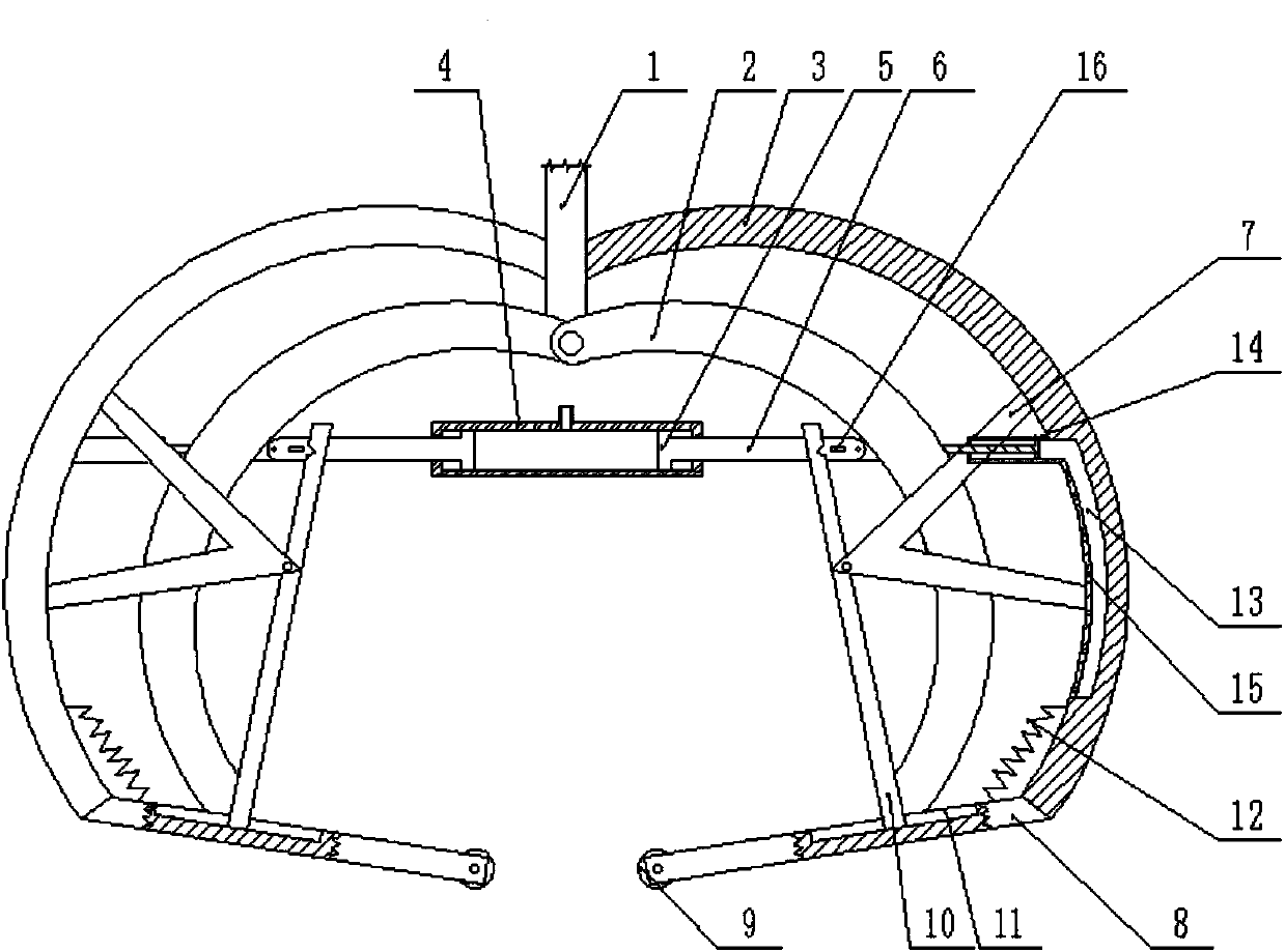
[0020] The reference signs in the drawings of the description include: hoisting mechanism 1, right clamping claw 2, right support rod 3, cylinder barrel 4, right piston plate 5, right piston rod 6, right support frame 7, right pry bar 8, Roller 9, right connecting rod 10, right chute 11, back-moving spring 12, right air chamber 13, right cylinder 14, air hole 15, right hook 16.

[0021] The embodiment is basically as figure 1 Shown: a crane maintenance spreader, including arc-shaped left clamping claw and right clamping claw 2, the upper ends of the left clamping claw and right clamping claw 2 are hinged to each other, and the hinge is fixedly connected with a lifting mechanism 1. The left and right piston rods 6 are respectively hinged on the opposite sides of the left clamping claw and the right clamping claw 2, and the opposite ends of the piston rod and the right piston rod 6 ar...


PUM


Abstract

The invention belongs to the technical field of load hanging elements or devices, and particularly discloses a lifting appliance for crane maintenance. The lifting appliance comprises a clamping mechanism, a lifting mechanism, a prying mechanism and a driving mechanism. According to the lifting appliance, to-be-lifted parts can be pried through the prying mechanism, thus the pried to-be-lifted parts can be easily clamped and positioned by the clamping mechanism and moved to the target position through the lifting mechanism, and the clamping mechanism and the prying mechanism are both driven bythe driving mechanism. The problem that in the prior art, a lifting appliance directly makes contact with the ground, and thus the lifting appliance is seriously abraded is solved.

Description

technical field [0001] The invention belongs to the technical field of load hanging components or devices, and specifically discloses a lifting tool for crane maintenance. Background technique [0002] The volume and weight of many large-scale equipment parts are much larger than common parts. Therefore, when these parts are repaired, after removing their connecting parts, they need to be hoisted to the ground by a crane for maintenance or repair steps. During the hoisting process, the parts to be repaired need to be fixedly connected with the spreader, and then the parts can be hoisted, which adds a step of fixed connection with the spreader to the maintenance process, which reduces the maintenance efficiency. [0003] In order to solve the above problems, a new type of maintenance sling has appeared in the prior art. A clamp is added to the sling, and the parts are clamped by the clamp for hoisting, which saves the steps of manual connection with the sling and improves the...

Claims


Application Information

Patent Timeline
Patent Type & Authority Applications(China)
IPC IPC(8): B66C1/28
CPCB66C1/28
Inventor 寇瑞东
Owner 徐州天骋智能科技有限公司
Why Eureka
Try Eureka