
Radon transform-based moving object imaging method, device and electronic device

A technology for moving targets and imaging methods, applied in measuring devices, radio wave measurement systems, radio wave reflection/re-radiation, etc., can solve the problem of positioning and imaging results of moving targets, accuracy reduction, defocusing and azimuth position deviation and other problems to achieve the effect of solving the asymmetry of the azimuth side lobes, improving the accuracy, and avoiding a large amount of calculation

Active Publication Date: 2018-05-18
SHIJIAZHUANG TIEDAO UNIV
View PDF4 Cites 22 Cited by
  • Summary
  • Abstract
  • Description
  • Claims
  • Application Information

AI Technical Summary

Problems solved by technology

[0003] However, due to the uncertain motion of the SAR carrier platform itself, the moving target will be defocused and azimuth position shifted on the SAR image, especially when the radial velocity of the moving target exceeds a certain value, it will lead to The accuracy of localization and imaging results is greatly reduced

Method used


Image

  • Radon transform-based moving object imaging method, device and electronic device
  • Radon transform-based moving object imaging method, device and electronic device
  • Radon transform-based moving object imaging method, device and electronic device

Examples


Embodiment Construction

[0031] In the following description, for the purpose of illustration rather than limitation, specific details such as a specific system structure and technology are proposed for a thorough understanding of the embodiments of the present invention. However, it should be clear to those skilled in the art that the present invention can also be implemented in other embodiments without these specific details. In other cases, detailed descriptions of well-known systems, devices, circuits, and methods are omitted to avoid unnecessary details from obstructing the description of the present invention.

[0032] In order to illustrate the technical solution of the present invention, specific embodiments are used for description below.

[0033] It should be pointed out that in a SAR system, the radial velocity will cause the Doppler center frequency of the moving target to shift, and different radial velocities will introduce different offsets, the Doppler center frequency shift It is proport...


PUM


Abstract

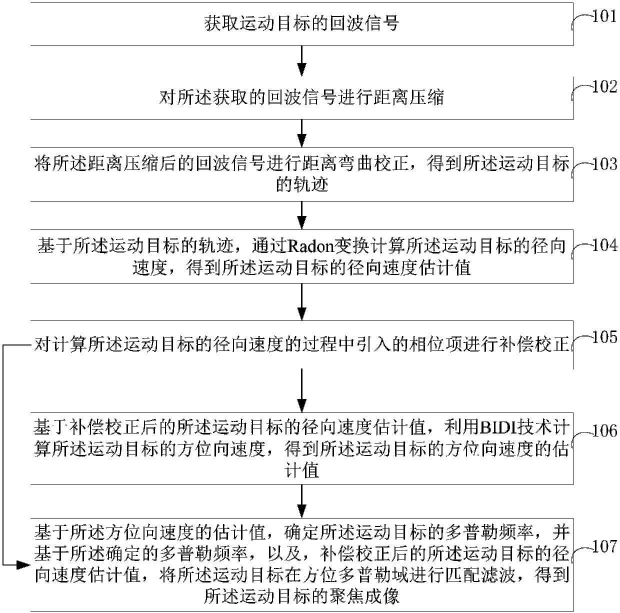
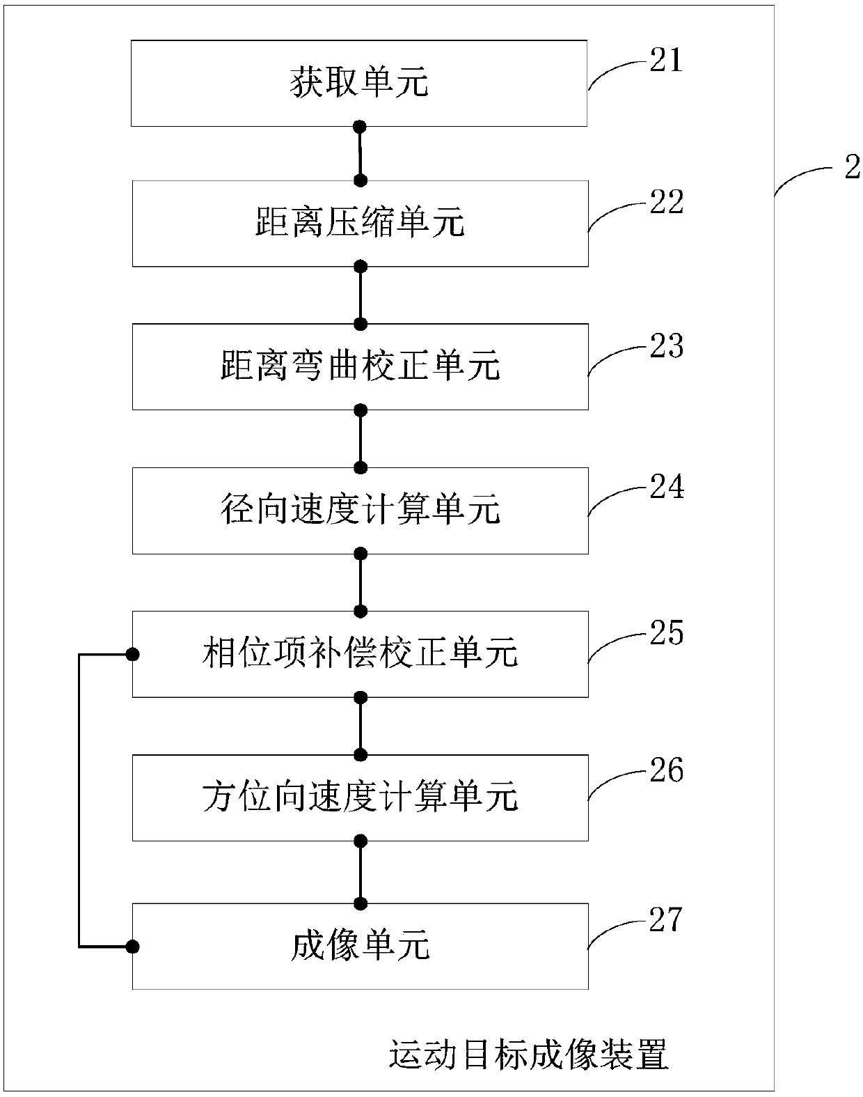
The present invention belongs to the radar identification technological field and provides a Radon transform-based moving object imaging method, a Radon transform-based moving object imaging device, an electronic device, and a computer-readable storage medium. The imaging method includes the following steps that: the echo signals of a moving object are obtained; distance compression is performed on the acquired echo signals; distance bending correction is performed; the radial velocity of the moving target is calculated through Radon transform; a phase term introduced into a calculation process is compensated and corrected; and the azimuth velocity of the moving target is calculated through using a BIDI technique; and matched filtering is performed on the moving target in the azimuth Doppler domain, so that the focused imaging of the moving target can be obtained. With the imaging method of the invention adopted, the accuracy of the positioning and imaging result of the moving target can be improved.

Description

Technical field [0001] The invention belongs to the technical field of synthetic aperture radar signal processing, and in particular relates to a moving target imaging method, device, electronic equipment and computer readable storage medium based on Radon transform. Background technique [0002] Synthetic Aperture Radar (SAR) is an active earth observation system that can be installed on aircraft (airborne), satellites (spaceborne) and other flight platforms. The SAR system uses the principle of synthetic aperture to achieve high Resolving microwave imaging can observe the ground all the time and all the time, and has a certain surface penetration ability. With the development of technology, synthetic aperture radars mounted on various platforms such as missile-borne, ground-based SAR, unmanned aerial vehicle SAR, near-space platform SAR, and handheld devices have emerged, which are widely used in military and civilian fields. [0003] However, due to the uncertain movement of th...

Claims


Application Information

Patent Timeline
IPC IPC(8): G01S13/90
CPCG01S13/904G01S13/9052G01S13/9029
Inventor 侯丽丽张骞朴春慧刘玉红
Owner SHIJIAZHUANG TIEDAO UNIV
Learn More