A kind of vortex beam detector and its preparation method

A vortex beam and detector technology, applied in optical device exploration, instrumentation, optics, etc., can solve problems such as damage, severe wavelength dependence, and crosstalk modes

Active Publication Date: 2019-09-06
NANJING UNIV
View PDF6 Cites 0 Cited by
  • Summary
  • Abstract
  • Description
  • Claims
  • Application Information

AI Technical Summary

Problems solved by technology

[0004] The invention provides a vortex beam detector and its preparation method to solve the serious dependence of the detection efficiency on the wavelength, the crosstalk between different orbital angular momentums and the detected mode when detecting a vortex beam in a superposition state sabotage problem

Method used


Image

  • A kind of vortex beam detector and its preparation method
  • A kind of vortex beam detector and its preparation method
  • A kind of vortex beam detector and its preparation method

Examples


Embodiment 1

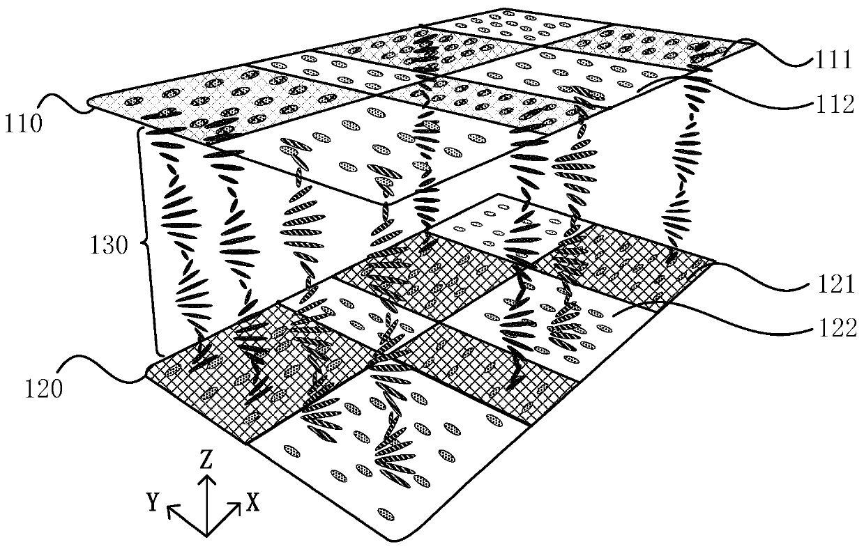
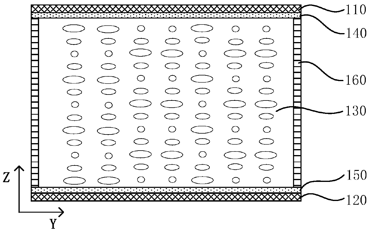
[0047] figure 1 It is a schematic diagram of a three-dimensional structure of a vortex beam detector provided in Embodiment 1 of the present invention, figure 2 It is a schematic diagram of a Y-Z side structure of a vortex beam detector provided in Embodiment 1 of the present invention. see figure 1 with figure 2 , the vortex beam detector includes:

[0048] The first substrate 110 and the second substrate 120 arranged oppositely; the cholesteric liquid crystal layer 130 between the first substrate 110 and the second substrate 120; the side of the first substrate 110 close to the second substrate 120 is formed with a first orientation Film 140; the first alignment film 140 comprises a first alignment region 111 and a second alignment region 112, and the alignment film molecular directors of the first alignment region 111 and the second alignment region 112 are arranged orthogonally; along the first direction ( figure 1 In the X direction), the first alignment region 111 ...

Embodiment 2

[0080] Figure 12 It is a schematic flow chart of a method for preparing a vortex beam detector provided in Embodiment 2 of the present invention, which is used to prepare the vortex beam detector provided in Embodiment 1 above. See Figure 12 , the preparation method comprises:

[0081] S510, providing a first substrate and a second substrate, where the first substrate and the second substrate are arranged opposite to each other.

[0082] Wherein, the first substrate and the second substrate can adopt flexible substrates or rigid substrates with high light transmittance (greater than or equal to 85%).

[0083] Exemplarily, the material of the first substrate and the second substrate may include quartz glass or ordinary glass, and the thickness of the substrate may be 1-2 millimeters (mm).

[0084] S520, forming a first alignment film on a side of the first substrate close to the second substrate, and forming a second alignment film on a side of the second substrate close to...


PUM

PropertyMeasurementUnit
thicknessaaaaaaaaaa
thicknessaaaaaaaaaa
reflectanceaaaaaaaaaa

Abstract

The invention discloses a vortex light beam detector and a preparation method thereof. The vortex light beam detector comprises a first substrate and a second substrate which are oppositely disposed and a cholesteric phase liquid crystal layer disposed between the first substrate and the second substrate. According to the vortex light beam detector, a first alignment film is formed on the side, close to the second substrate, of the first substrate and includes first alignment areas and second alignment areas, and alignment film molecules in the first alignment areas and the second alignment areas are oriented in a vector orthogonal array to form a Daman fork-like grating; a second alignment film is formed on the side, close to the first substrate, of the second substrate and disposed correspondingly to control a spiral structure of cholesteric phase liquid crystals between the two substrates to be twisted at 90 degrees in an array in neighboring areas to form a two-dimensional Daman fork-like grating based on the cholesteric phase liquid crystals, so that wide-band, high-efficiency, on-line nondestructive detection of vortex light beams by the detector is achieved, crosstalk between angular momentum of different tracks is avoided at the same time, and the detection capacity of the detector is increased.

Description

technical field [0001] Embodiments of the present invention relate to the technical field of microstructure liquid crystals and vortex beams, in particular to a vortex beam detector and a preparation method thereof. Background technique [0002] Compared with plane waves or Gaussian beams, vortex beams have a spiral phase distribution, and the central phase singularity leads to a dark field, which generally presents a hollow annular distribution. This special helical wavefront introduces the orbital angular momentum of light, bringing a new degree of freedom to the manipulation of light. In recent years, the application research of vortex beams in the fields of optical tweezers, super-resolution microscopic imaging, laser processing, optical communication and quantum information has emerged in an endless stream, and is gradually moving from experimental research to production and life. Among them, the most eye-catching is the optical communication technology based on the mu...

Claims


Application Information

Patent Timeline
Patent Type & Authority Patents(China)
IPC IPC(8): G02B5/18G02F1/1337G02F1/1339G02F1/137G01V8/10
CPCG01V8/10G02B5/1866G02F1/1337G02F1/133788G02F1/13392G02F1/13394G02F1/13718G02F1/13398
Inventor 胡伟陈鹏马玲玲段薇葛士军陆延青徐飞
Owner NANJING UNIV
Why Eureka
Try Eureka