User interface component generation method and device

A user interface and component technology, applied in the computer field, can solve problems such as high coupling of business modules, high cost of browser rendering, poor system scalability, and poor maintainability, and achieve high efficiency, simple operation, and reduced coupling.

Active Publication Date: 2018-05-18
深圳市四格互联信息技术有限公司
View PDF9 Cites 43 Cited by
  • Summary
  • Abstract
  • Description
  • Claims
  • Application Information

AI Technical Summary

Problems solved by technology

However, the existing solutions have the following defects: developers need to operate the document object model one by one, the operation is complicated and inefficient, and the browser rendering cost is high during the generation pr

Method used


Image

  • User interface component generation method and device
  • User interface component generation method and device
  • User interface component generation method and device

Examples


Embodiment approach 1

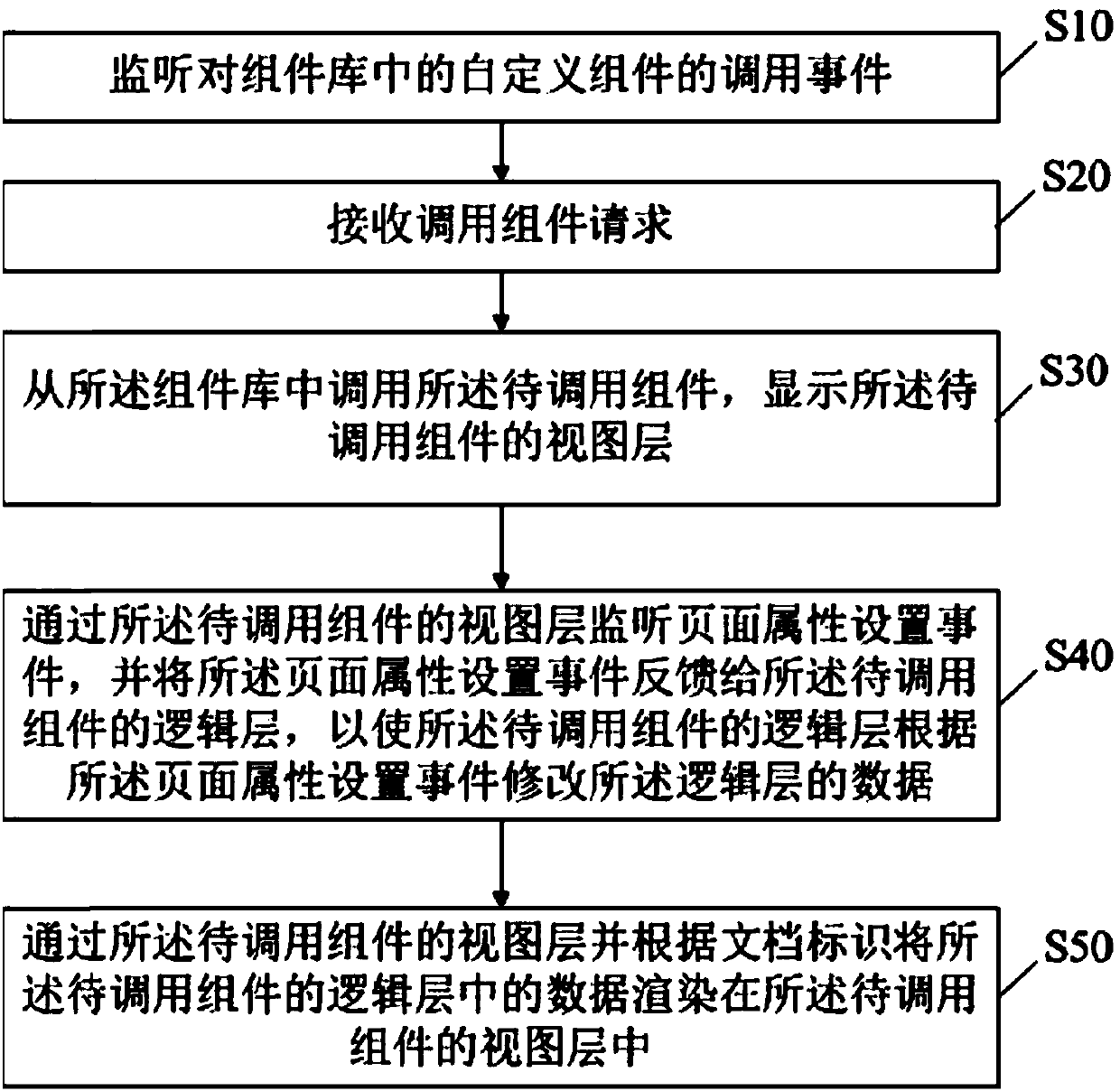
[0121] Embodiment 1: The developer draws a rectangular area on the background image: after clicking the left mouse button, drag the mouse to the verification position, and release the mouse to form a rectangle. At this time, when the view layer receives two coordinates, the logic layer uses the rectangular area formed by the diagonal coordinates of the two coordinate points as a rectangle as the area framed by the area.

Embodiment approach 2

[0122] Embodiment 2: The developer draws a polygonal area on the background image: after clicking the left mouse button, drag the mouse to the verification position, click the left button again to generate nodes, and connect each node to form a closed graph. At this time, when the view layer receives more than three coordinates, and the distance between the start coordinates and the end coordinates is less than the lower limit threshold, the logic layer uses the received coordinates as corner points to form a polygonal area as the The area range of the area frame selection.

Embodiment approach 3

[0123] Implementation Mode 3: The developer adjusts the range of the above-mentioned frame-selected area on the background image: click the selected area with the mouse, and a circular adjustment point will appear at the coordinate point of the area, and the graphics can be adjusted by dragging the adjustment point. At this time, the view layer listens to the adjustment event of the frame selection of the area; the adjustment event includes the operation of clicking the corner point of the frame selection of the area with the mouse, the operation of dragging the corner point of the mouse, and the operation of releasing the frame selection of the mouse. operation of the corner points. When the view layer receives the coordinates when the mouse releases the corner point, the logic layer replaces the coordinates of the corner point with the received coordinates to complete the adjustment of the area frame selection.


PUM


Abstract

The embodiment of the invention discloses a user interface component generation method and device. The method comprises the steps that a component library is uploaded, and components in the componentlibrary is called, wherein the component library comprises a search box, a data and time selector, a tree component, a pop-up box, image polygon hot area drawing and the like; when one component is called from the component library, the component is displayed on a display interface, a view layer of the component monitors a page attribute set event requested to be executed by a developer, and the event is fed back to a logical layer of the component, so that data of the logical layer is modified according to the page attribute set event. Due to the fact that document identification of page elements of the view layers of the components and document identification of the data processed by the logical layers are bound, the view layers only need to render the data in the logical layers of the to-be-called components in the view layers of the components according to the document identification, that is to say, custom adjustment on the components can be completed, the operator does not need to operate document object models one by one, operation is easy, and the efficiency is high.

Description

technical field [0001] The invention relates to the field of computer technology, in particular to a method and device for generating user interface components. Background technique [0002] With the increasing number of handheld smart devices, user interaction and experience requirements for web pages have been significantly improved. While developing a large-scale background management system, R&D personnel need to develop their respective business interfaces in parallel, that is, web interfaces, so that users can interact with the management system through the web interfaces. During the development process, R&D personnel control the background management system and business interface to maintain low coupling, and at the same time ensure the consistency of interface interaction. There are not many frameworks on the market that can meet such requirements. Generally, Bootstrap based on jquery.js is commonly used. [0003] The process of using Jquery.js to generate the inter...

Claims


Application Information

Patent Timeline
IPC IPC(8): G06F9/451G06F8/38
CPCG06F8/38
Inventor 梁建新郭敏旋邱全虎王雷
Owner 深圳市四格互联信息技术有限公司
Why Eureka
Try Eureka