
Fire monitoring alarm system of mobile terminal

A fire alarm system and mobile terminal technology, applied in the direction of electric fire alarms, fire alarms that rely on radiation effects, fire alarms that rely on smoke/gas effects, etc., can solve uneconomical, hysteresis, and inability to guarantee Data security and other issues, to achieve the effect of simple structure

Inactive Publication Date: 2018-05-18
GUANGZHOU JINGTONG ELECTROMECHANICAL EQUIP CO LTD
View PDF4 Cites 2 Cited by
  • Summary
  • Abstract
  • Description
  • Claims
  • Application Information

AI Technical Summary

Problems solved by technology

Therefore, the disadvantages of the existing technology are: 1. The fire monitoring and alarm device is installed in a remote place, not on the power distribution cabinet, and has hysteresis, and measures can only be taken when a fire has occurred; 2. The power supply circuit cannot be online in real time monitor
[0003] In the prior art, when the equipment manager sets up the electrical fire monitoring system and the electric power monitoring system respectively, the two sets of monitoring systems require multiple electrical fire monitoring devices and multiple power monitoring devices. Due to the structure of the two sets of monitoring systems Similar, and the electrical fire parameters and power operation parameters include the same monitoring parameters, such as current, voltage, and temperature. The use of RS485 serial communication will also lead to communication blocking during the communication process. For the equipment management side, it is neither economical nor can it guarantee data security.

Method used


Image

  • Fire monitoring alarm system of mobile terminal

Examples


Embodiment Construction

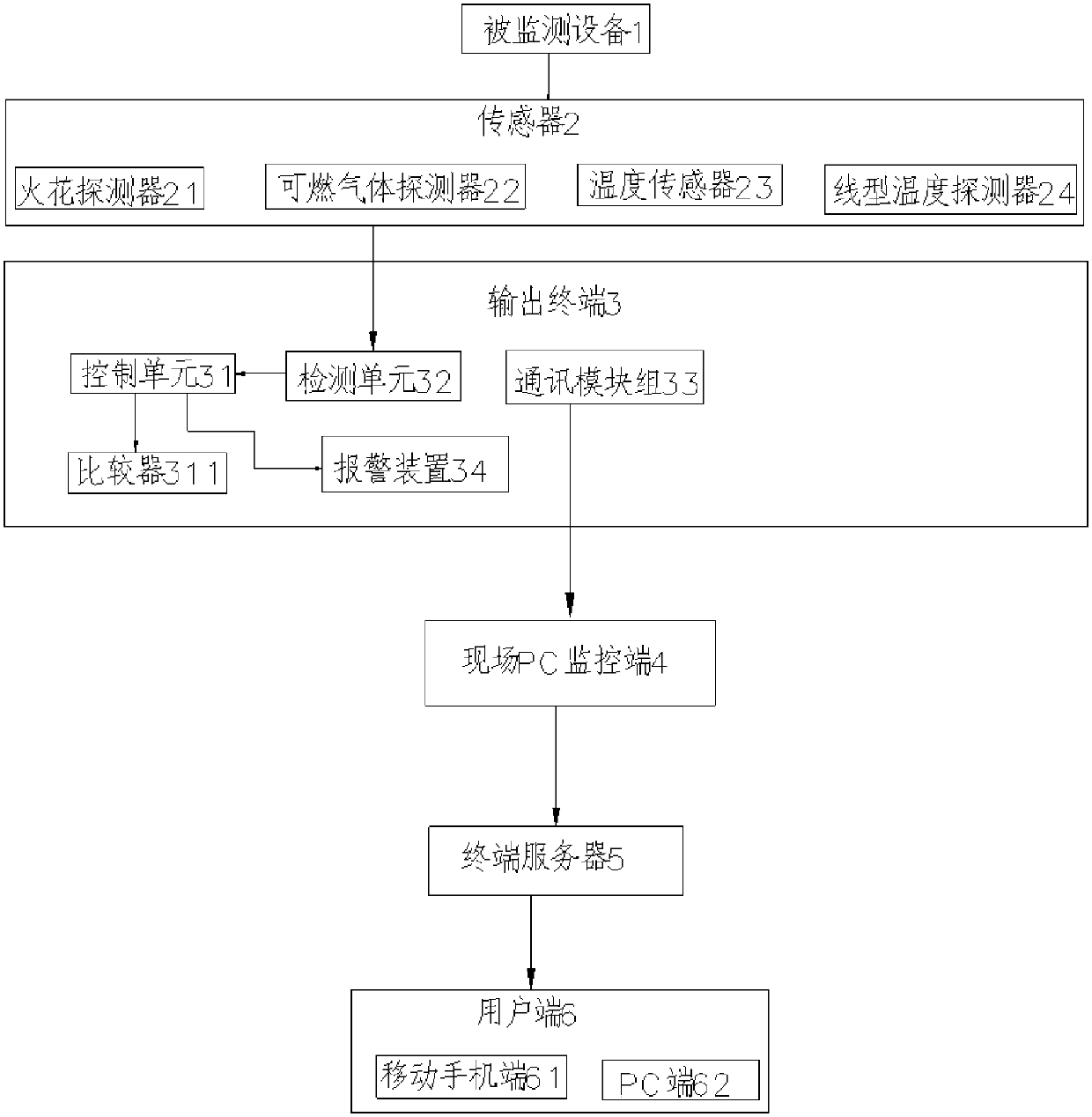
[0022] Such as figure 1 As shown, the technical solution adopted by the present invention is: a mobile terminal monitorable fire alarm system, which is characterized in that it includes several monitored devices 1, several on-site PC monitoring terminals 4, terminal servers 5, and several user terminals 6, and also includes A number of sensors 2 on site and an output terminal 3 that integrates the sensor signals and sends them to the PC monitoring terminal 4 on site.

[0023] Preferably, the user terminal 6 is a mobile phone terminal or 61 PC terminal 62 .

[0024] Preferably, several on-site PC monitoring terminals 4 transmit information to the terminal server 5 through the Internet, and after the terminal server 5 accepts and processes the data, the user checks real-time or historical data through the client terminal 6.

[0025] Preferably, the sensor 2 is arranged on the monitored equipment on site, and is used to obtain temperature status information of the monitored equi...


PUM


Abstract

The invention discloses a fire monitoring alarm system of a mobile terminal. The system adopts a common sensors widely used in the market for obtaining various data such as temperature, oxygen concentration, dust concentration, delay, flame, spark and the like, and the real-time monitoring requirements of various occasions can be met. The data of a sensor monitoring channel can be processed through a control module, and the data of the sensor monitoring channel can be displayed on an on-site PC monitoring terminal. Rich contents, such as a real-time curve, various data display screens and alarm lists, can be checked on the system, and the monitoring result is clear at a glance. The system automatically generates a data list, the panel is provided with a USB interface, and historical data can be transferred, and an upper computer software can call the characteristic values, the corresponding time, the valley value of all the channels in the set time of a user, and the corresponding timecan be generated, and a channel log can be generated. Real-time data can be synchronously output to a terminal device through RS-485 or the Ethernet. Remote monitoring is facilitated. The system canbe connected with the mobile terminal through an intermediate server, and the user can monitor the operation state of the system in real time.

Description

technical field [0001] The invention relates to the field of intelligent monitoring, in particular to a mobile terminal monitorable fire alarm system. Background technique [0002] Electrical safety issues have become a major concern in various industries, especially in high-rise apartments, petrochemicals, airports, telecommunications and other fields. Therefore, it is necessary for the power distribution cabinet to have electrical fire monitoring functions. If the power distribution cabinet currently used needs to cut off the power supply manually if an electrical fire occurs; there is also a simple fire alarm device used in the distance. Therefore, the disadvantages of the existing technology are: 1. The fire monitoring and alarm device is installed in a remote place, not on the power distribution cabinet, and has hysteresis, and measures can only be taken when a fire has occurred; 2. The power supply circuit cannot be online in real time monitor. In order to ensure the...

Claims


Application Information

Patent Timeline
Patent Type & Authority Applications(China)
IPC IPC(8): G08B17/12G08B17/10G08B17/06
CPCG08B17/12G08B17/06G08B17/10
Inventor 唐彤
Owner GUANGZHOU JINGTONG ELECTROMECHANICAL EQUIP CO LTD
Learn More