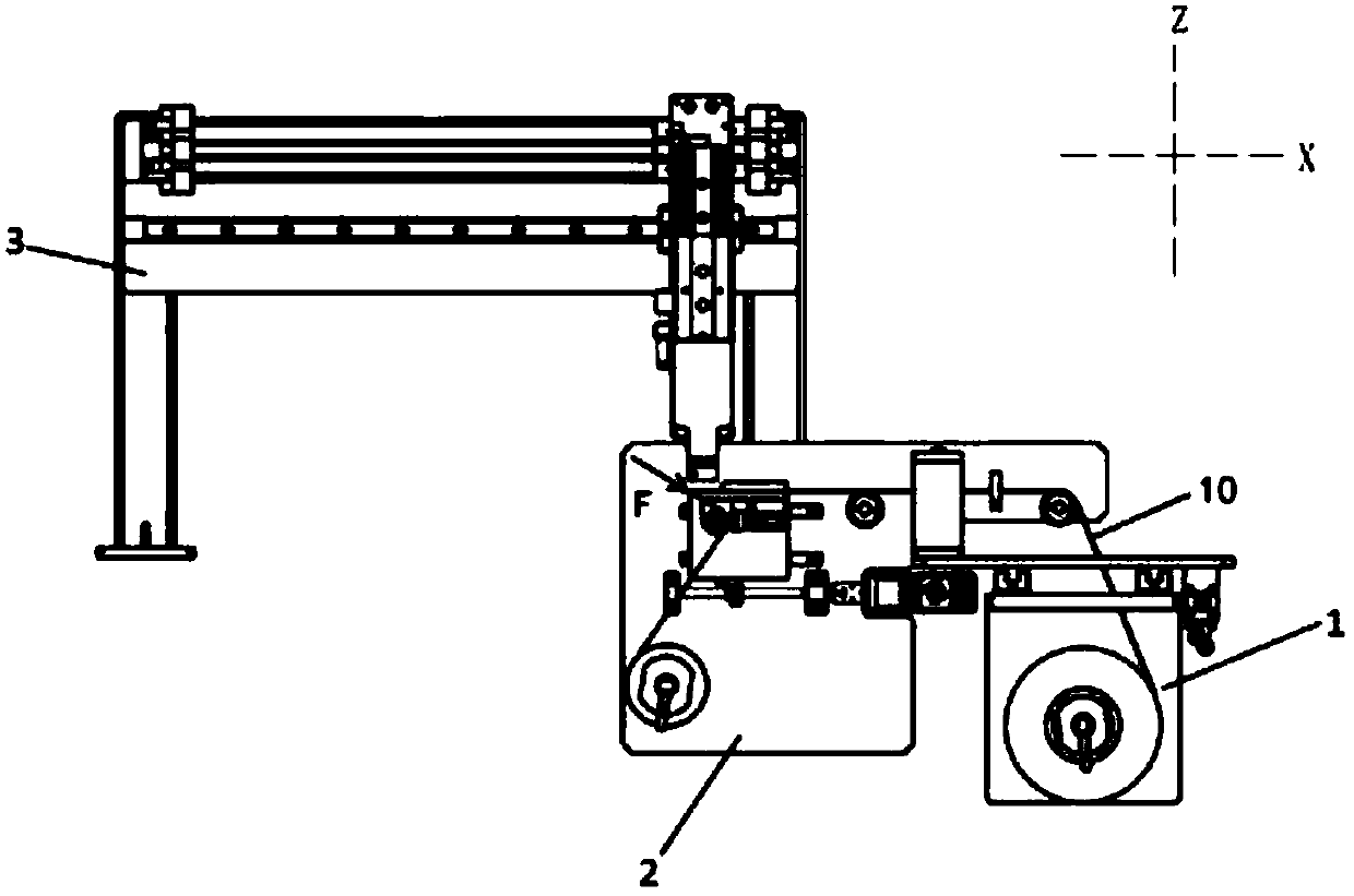
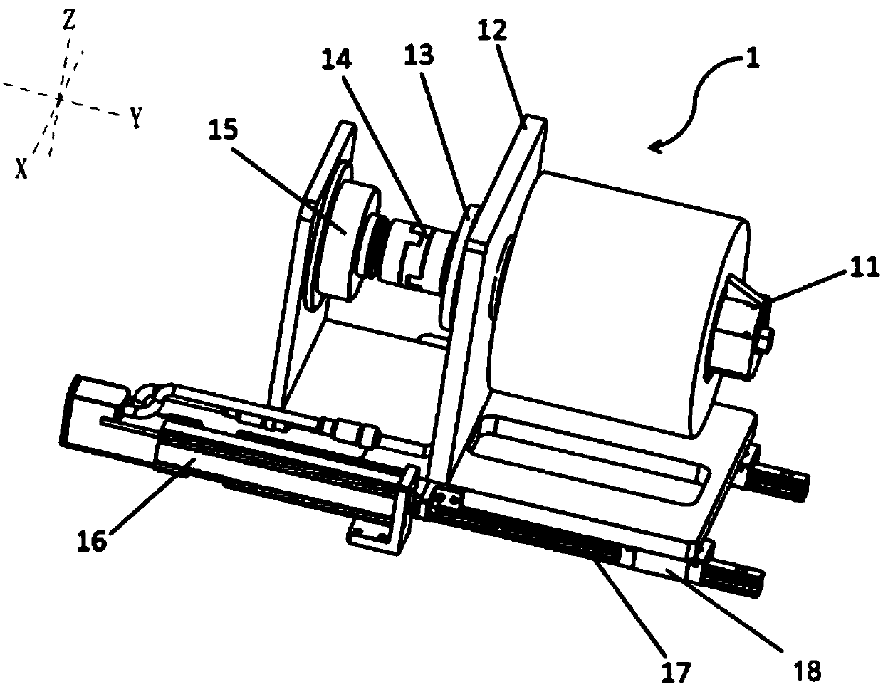
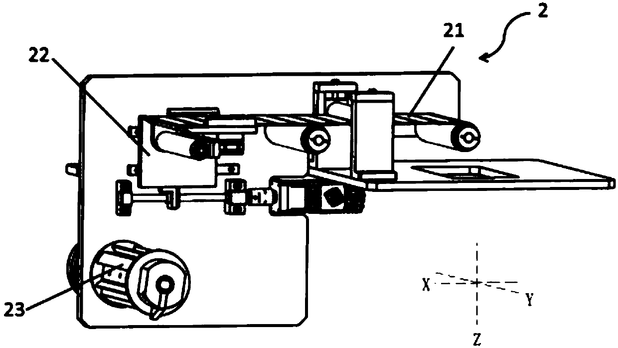
Unpowered unreeling machine, cell top surface protecting film tearing device, film adhering device and film adhering method

A technology of unwinding machine and protective film, which is applied to circuits, electrical components, secondary batteries, etc., can solve the problems of unguaranteed film quality, inability to wrap on a cylindrical surface, immature technology, etc., to simplify electrical control and ensure stability. The effect of high stability and simple unwinding structure

Pending Publication Date: 2018-05-18
SUZHOU JEE INTELLIGENT EQUIP CO LTD
View PDF0 Cites 3 Cited by
  • Summary
  • Abstract
  • Description
  • Claims
  • Application Information

AI Technical Summary

Problems solved by technology

[0004] The existing coating process is: wrap the battery core with a continuous insulating film, but due to the particularity of the pole surface, it cannot be wrapped with a continuous film, and it needs to be wrapped with a separate insulating sticker
[0005] In the past production process, most of the film lamination equipment, such as the battery cell automatic encapsulation machine disclosed in Chinese patent 2015200952955, can only encapsulate several surfaces of the depolarization cylinder surface of the battery cell, but cannot enclose the pole. There are certain risks in this way; some production factories choose to stick the film manually, so the production efficiency is low, and the quality of the film cannot be guaranteed; due to the lack of equipment for separating the insulating sticker from the bottom film, the relevant technology is not mature, resulting in the top surface of the battery core being damaged. Automatic film sticking has become an urgent problem to be solved

Method used


Image

  • Unpowered unreeling machine, cell top surface protecting film tearing device, film adhering device and film adhering method
  • Unpowered unreeling machine, cell top surface protecting film tearing device, film adhering device and film adhering method
  • Unpowered unreeling machine, cell top surface protecting film tearing device, film adhering device and film adhering method

Examples


Embodiment Construction

[0045] Objects, advantages and features of the present invention will be illustrated and explained by the following non-limiting description of preferred embodiments. These embodiments are only typical examples of applying the technical solutions of the present invention, and all technical solutions formed by adopting equivalent replacements or equivalent transformations fall within the protection scope of the present invention.

[0046] In the description of the scheme, it should be noted that the terms "center", "upper", "lower", "left", "right", "front", "rear", "vertical", "horizontal", " The orientation or positional relationship indicated by "inner", "outer", etc. is based on the orientation or positional relationship shown in the drawings, and is only for the convenience of description and simplification of description, rather than indicating or implying that the device or element referred to must have a specific orientation , constructed and operated in a particular or...


PUM


Abstract

The invention discloses an unpowered unreeling machine, a cell top surface protecting film tearing device, a film adhering device and a film adhering method. The unpowered unreeling machine comprisesan unreeling shaft for placing a reeled material; the unreeling shaft is rotatably arranged on a support frame through a bearing; the unreeling shaft is connected with a limiter which limits rotationof the unreeling shaft; when the tensile force applied to the reeled material is smaller than the torque limited value of the limiter, the unreeling shaft does not rotate; and when the tensile force applied to the reeled material is greater than torque limitation of the limiter, the unreeling shaft rotates. According to the unpowered unreeling machine, the degree of freedom of rotation of the unreeling shaft is limited by the limiter, therefore, the problem that follow-up processing is affected by unreeling of the reeled material due to the rotation inertia of the unreeling shaft or the tensile force when the unreeling shaft does not work can be avoided, and thus, a foundation is laid for development and utilization of the cell top surface film adhering equipment; and moreover, an unreeling mode is optimized into magnetic powder brake unreeling from traditional motor unreeling, the unreeling structure is simple, and electrical control of unreeling is greatly simplified.

Description

technical field [0001] The invention relates to the field of electric core processing, in particular to a non-powered unwinding machine, a film tearing device for the protective film on the top surface of the electric core, a film sticking device and a film sticking method. Background technique [0002] With the continuous development of society and continuous advancement of science and technology, mechanization, automation and standardization of production have gradually become a development trend. As a high-tech emerging industry, the lithium battery industry has stricter control over the production process. It is an inevitable trend for the development of enterprises to use automated machinery and equipment to eliminate uncontrollable manual operations. [0003] During the production and use of batteries, safety is the first priority. When the two poles of the battery are in contact with the conductor and there is a short circuit, the battery may explode and cause a safet...

Claims


Application Information

Patent Timeline
IPC IPC(8): H01M10/04H01M10/0587
CPCH01M10/0404H01M10/0587Y02E60/10Y02P70/50
Inventor 张正初韩志荣朱涛王思伟
Owner SUZHOU JEE INTELLIGENT EQUIP CO LTD
Why Eureka
Try Eureka