Separated-closed type multi-head stirring rod manufacturing and installation process

An installation process and stirring rod technology, which is applied in the field of manufacturing and installation process of split-type multi-head stirring rods, can solve the problems of not ensuring product quality, requiring product functions, and single production and manufacturing.

Inactive Publication Date: 2018-05-22
QINGDAO CENTURY YUNFAN IND
View PDF0 Cites 0 Cited by
  • Summary
  • Abstract
  • Description
  • Claims
  • Application Information

AI Technical Summary

Problems solved by technology

[0002] Each product has its unique production and processing methods, and the different structures and materials of the product will also have a very different installation process from other products. According to the characteristics of the product, a more complete and most suitable production and installation process can be made. There are fewer detours in the production and installation process, and at the same time, it can save manpower, material resources and raw materials, and produce high-quality and low-cost products safely and quickly. The split-and-close multi-head stirring rod is a non-standard product, so the production of the product is single. This determines that the production and manufacture of components must have its special manufacturing process, otherwise the quality requirements and functions of the product cannot be guaranteed

Method used


Image

  • Separated-closed type multi-head stirring rod manufacturing and installation process
  • Separated-closed type multi-head stirring rod manufacturing and installation process

Examples


Embodiment Construction

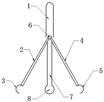
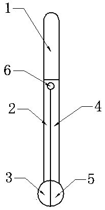
[0009] The present invention will be further described below in conjunction with accompanying drawing.

[0010] Taking the split multi-head stirring rod as an example, stainless steel raw materials are used to cast a handle 1, a middle stirring rod 7, a spherical stirring head 8, and a left and right movable semicircular stirring rod 2 with left and right semicircular stirring heads 4 and 5. , 3 Blank parts - handle 1, middle stirring rod 7, spherical stirring head 8 integrated blank and left and right movable semicircular stirring rods with left and right, semicircular stirring heads 4, 5 2, 3 Surface removal of casting burrs and polishing —Drilling and polishing the upper ends of middle stirring rod 7, left and right movable semicircular stirring rods 2 and 3—integrate the upper end of middle stirring rod 7 with connecting shaft 6 and left and right movable semicircular stirring rods 2 and 3—overall visual inspection —Manual experiment: choose one stirring head or separate t...


PUM


Abstract

A separated-combined type multi-head stirring rod manufacturing and installation process comprises that a grab handle, middle stirring rod and spherical stirring head integral blank, a right movable semicircle stirring rod blank with a right semicircle stirring head, and a left movable semicircle stirring rod blank with a left semicircle stirring head are casted from a stainless steel raw material; the surfaces of the grab handle, middle stirring rod and spherical stirring head integral blank, the right movable semicircle stirring rod blank with the right semicircle stirring head and the leftmovable semicircle stirring rod blank with the left semicircle stirring head have casting burrs removed and are polished; the upper ends of a middle stirring rod, the left movable semicircle stirringrod and the right movable semicircle stirring rod are bored and are subjected to finishing polishing; the upper end of the middle stirring rod 7 is mounted into a whole with the left movable semicircle stirring rod 2 and the right movable semicircle stirring rod 3 through a connection shaft 6; overall appearance inspection is performed; and manual experiments are performed. The separated-combinedtype multi-head stirring rod manufacturing and installation process can perform orderly production and installation according to the standard so as to ensure the manufacture quality and requirements of products, reduces unrelated and unnecessary links, can save the raw materials, and reduces the cost; the processing and installation production process observes all rules and regulations and is safeand orderly.

Description

technical field [0001] The invention relates to a process for making a tool for fully stirring a mixed liquid in a chemical experiment, that is, a manufacturing and installing process for a split-and-combined multi-head stirring rod. Background technique [0002] Each product has its unique production and processing methods, and the different structures and materials of the product will also have a very different installation process from other products. According to the characteristics of the product, a more complete and most suitable production and installation process can be made. There are fewer detours in the production and installation process, and at the same time, it can save manpower, material resources and raw materials, and produce high-quality and low-cost products safely and quickly. The split-and-close multi-head stirring rod is a non-standard product, so the production of the product is single. This determines that the production and manufacture of components ...

Claims


Application Information

Patent Timeline
Patent Type & Authority Applications(China)
IPC IPC(8): B01F15/00
CPCB01F27/054B01F2101/23
Inventor 赵岳鹏
Owner QINGDAO CENTURY YUNFAN IND
Why Eureka
Try Eureka