Assembling device and assembling method of automobile vacuum booster and brake master cylinder

A technology of vacuum booster and brake master cylinder, which is applied in measuring devices, instruments, assembly machines, etc., can solve the problems of time-consuming, error, and low accuracy.

Pending Publication Date: 2018-05-22
WENZHOU RUILI KEMI AUTOMOTIVE ELECTRONICS CO LTD
View PDF11 Cites 2 Cited by
  • Summary
  • Abstract
  • Description
  • Claims
  • Application Information

AI Technical Summary

Problems solved by technology

[0004] The current assembly method is to manually measure the gap through the depth gauge and vernier caliper, and then add suitable gaskets for assembly, which is laborious and time-consuming; due to errors and limitations caused by manual measurement, the accuracy is not high. Difficult to control quality
[0005] The Chinese utility model patent whose publication number is CN203566224U discloses a vacuum state zero-gap adjustment device for the docking of the brake master cylinder and the vacuum booster, which includes an adjustment frame, an adjustment rod, a nut locking assembly and a push rod pressing assembly; the nut lock The lower end of the adjustment sleeve of the tightening assembly passes through the central hole of the piston guide sleeve and the oil seal of the guide sleeve and extends out of the bottom of the chassis of the adjustment frame, and the bottom end is opened with a hexagonal inner hole of the lock nut; the lower end of the spring of the push rod compression assembly and the pressure seat Connection, the upper end is connected with the bottom of the installation cup; the lower part of the adjustment rod passes through the limit sleeve, the hand wheel and the center hole of the adjustment sleeve to slide and fit with the adjustment sleeve, the upper part of the adjustment rod passes through the middle plate of the adjustment frame, and the top of the adjustment rod is The semi-round head has a hexagonal inner hole for the adjustment screw at the bottom of the lower section. This adjustment device is aimed at adjusting the height of the screw and the gap between the rear piston of the master cylinder when the vacuum booster of the threaded push rod for vehicles is connected with the brake master cylinder. The sealing surface of the vacuum booster seals the front shell of the vacuum booster and the kinematic pair of the tooling to realize the adjustment of the adjusting screw of the booster in a vacuum state, and to achieve the consistency of the idle stroke of the assembly after the brake master cylinder and the vacuum booster are connected, but the mechanism of the adjusting device Problems such as settings and extra manual operations have resulted in no substantial improvement in assembly production efficiency and product quality after assembly

Method used


Image

  • Assembling device and assembling method of automobile vacuum booster and brake master cylinder
  • Assembling device and assembling method of automobile vacuum booster and brake master cylinder
  • Assembling device and assembling method of automobile vacuum booster and brake master cylinder

Examples


Embodiment 1

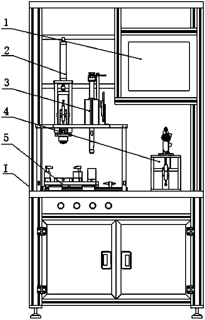
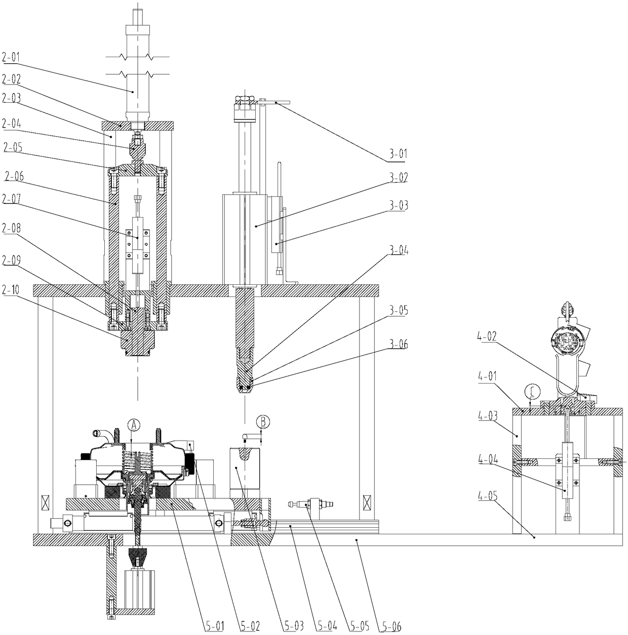
[0081] Such as figure 1 with figure 2 As shown, the assembly device of the automobile vacuum booster and the brake master cylinder includes an assembly frame body I, and the assembly frame body I is provided with a press-fit table, a PLC control device 1, and a distance measurement between the end face of the vacuum booster output rod and the end face of the rear housing. Device 2, output rod head length measuring device 3, brake master cylinder first piston depth measuring device 4, sliding table device 5, measuring button, press-fit button and power management device.

[0082] In the assembly device of the automobile vacuum booster and brake master cylinder described in this embodiment, the distance measuring device 2 between the end face of the output rod of the vacuum booster and the end face of the rear housing is connected to the PLC control device 1 for accurately measuring the The distance from the end face of the output rod of the vacuum booster to the installation en...

Embodiment 2

[0132] On the basis of the technical solution described in embodiment 1, the assembly frame body 1 of the assembly device of the automobile vacuum booster and the brake master cylinder is also provided with a retest button, and the retest button is connected to the PLC control device 1. The power management device is connected to the measurement button, the press-fit button, the retest button and the PLC control device 1 to provide power guarantee for the automatic press-fit process.

[0133] Set the retest button and add a retest link.

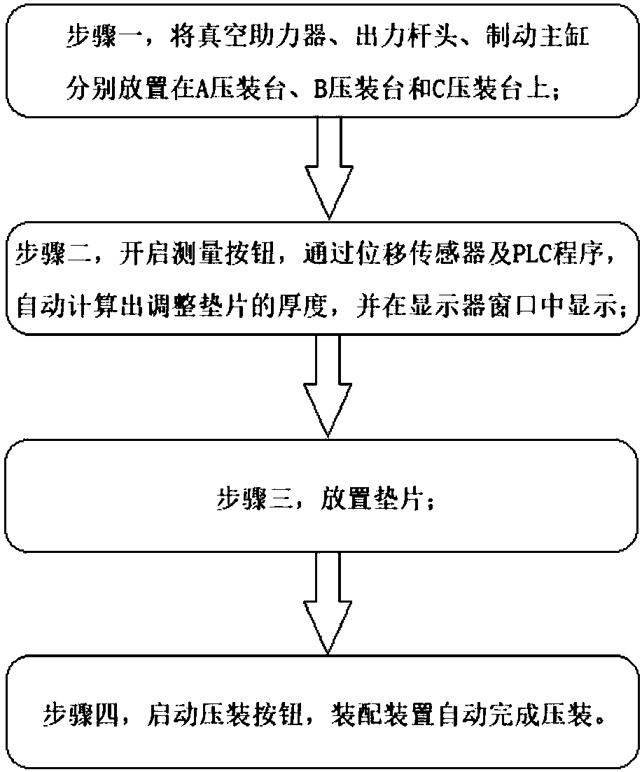
[0134] Such as Figure 4 As shown, a retesting step is added between steps 2 and 3 of the assembly method of the automobile vacuum booster and brake master cylinder: place the vacuum booster, the output rod head, and the brake master cylinder on three press-fitting stations respectively. On A, B, and C, turn on the measurement button, automatically calculate the thickness of the adjusting gasket through the displacement sensor and the PLC pr...


PUM


Abstract

The invention relates to an assembling device and an assembling method of an automobile vacuum booster and a brake master cylinder. The assembling device comprises an assembling rack body (I), and three press fitting tables, a PLC control device (1), a vacuum booster output lever end face and rear shell end face distance measurement device (2), an output lever head length measurement device (3), abrake master cylinder first piston depth measurement device (4) and a sliding table device (5) are arranged on the assembling rack body (I). The PLC control device (1) is used for respectively collecting the measured data of the vacuum booster output lever end face and rear shell end face distance measurement device (2), the output lever head length measurement device (3) and the brake master cylinder first piston depth measurement device (4), automatically working out the thickness of an adjusting shim, placing the proper shim, controlling the action of the sliding table device, and automatically completing press fitting. The amount of minimum clearance of the output lever of the vacuum booster and the first piston of the brake master cylinder during assembly is ensured, and the productquality and the production efficiency are improved.

Description

technical field [0001] The invention relates to the technical field of vehicle brake system fixtures and assembly, in particular to an assembly device and an assembly method for an automobile vacuum booster and a brake master cylinder. Background technique [0002] In a vehicle braking system, a vacuum booster is a component that uses vacuum to increase the force exerted by the driver on the pedal. The Chinese utility model patent with the publication number CN206049651U discloses a vacuum booster, the dust cover of which includes a circular thin-walled shell with corrugations, one end of the thin-walled shell is provided with an opening, and the other end is provided with a bottom. There is a central hole at the bottom, and rubber hoses are installed on the side wall of the bottom, which effectively avoids the pollution of poor-quality air in the atmosphere, greatly improves the harsh working environment of the existing protective cover, and greatly improves the overall sea...

Claims


Application Information

Patent Timeline
Patent Type & Authority Applications(China)
IPC IPC(8): B23P19/027B23P21/00G01B21/02G01B21/18
CPCG01B21/02G01B21/18B23P19/027B23P21/004
Inventor 韩学涛李传武杨柳蒋邵彬施明伟
Owner WENZHOU RUILI KEMI AUTOMOTIVE ELECTRONICS CO LTD
Why Eureka
Try Eureka