Auxiliary supporting device for milling machine

An auxiliary support and milling machine technology, applied in the direction of milling machine equipment, milling machine equipment details, large fixed members, etc., can solve the problems of inconvenient clamping of workpieces, and achieve the effect of stable force and easy movement

Inactive Publication Date: 2018-05-22
重庆臣凿科技有限公司
View PDF0 Cites 11 Cited by
  • Summary
  • Abstract
  • Description
  • Claims
  • Application Information

AI Technical Summary

Problems solved by technology

[0004] The purpose of the present invention is to provide an auxiliary support device

Method used


Image

  • Auxiliary supporting device for milling machine
  • Auxiliary supporting device for milling machine

Examples


Embodiment Construction

[0022] Further detailed explanation through specific implementation mode below:

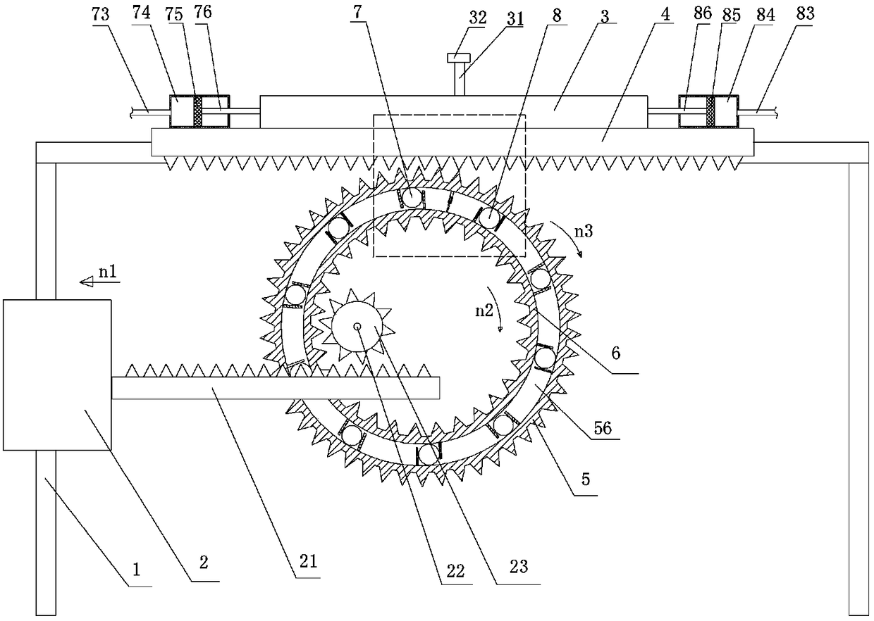
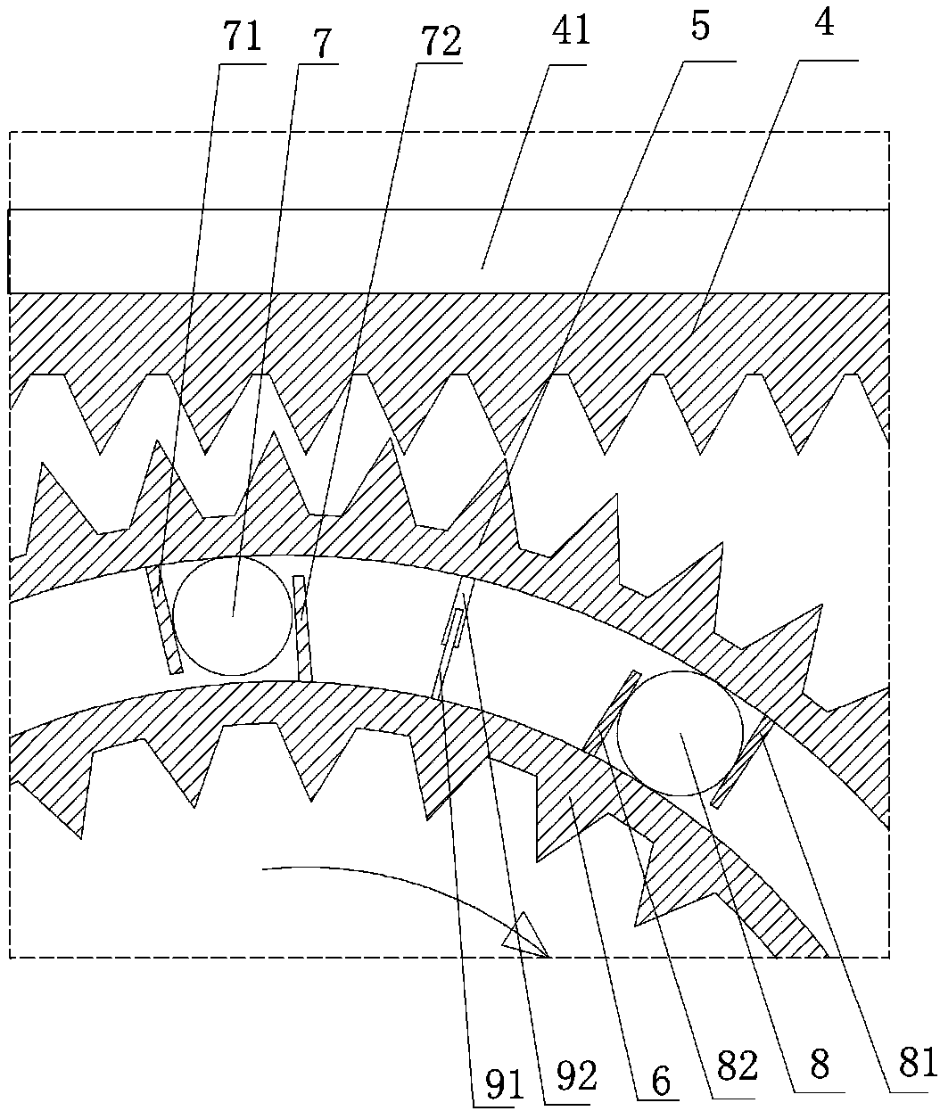
[0023] The reference signs in the accompanying drawings of the description include: supporting stand 1, workbench 2, second rack 21, first rotating shaft 22, gear 23, adjustment plate 3, support rod 31, positioning groove 32, first rack 4 , electromagnet 41, outer ring gear 5, detection cavity 56, inner ring gear 6, first air bag 7, first outer baffle 71, first inner baffle 72, first hose 73, first piston chamber 74, First piston 75, first piston rod 76, second air bag 8, second outer baffle 81, second inner baffle 82, second hose 83, second piston cavity 84, second piston 85, second piston The rod 86 , the second conductive sheet 91 , and the first conductive sheet 92 .

[0024] Such as figure 1 As shown, the milling machine auxiliary support device of this embodiment includes a support stand 1, a hollow first rack 4 is horizontally slidably disposed on the support stand 1, and an adjustment p...


PUM


Abstract

The invention belongs to the field of auxiliary equipment of milling machines, and particularly discloses an auxiliary supporting device for a milling machine. The auxiliary supporting device for themilling machine comprises a supporting platform. A first rack is slidably arranged on the supporting platform. An adjustment plate is slidably connected to the upper portion of the first rack. A firstpiston cavity and a second piston cavity are fixedly formed in the two ends of the first rack correspondingly. The surface, opposite to the first rack, of the adjustment plate is coated with magnetism conduction materials. The first rack is filled with an electromagnet and engaged with an outer gear ring. The outer gear ring is rotatably connected to the supporting platform. An inner gear ring isarranged in the outer gear ring in a sleeved mode. An annular detection cavity is formed between the outer gear ring and the inner gear ring. A first airbag, a second airbag, a first airbag squeezingmechanism and a second airbag squeezing mechanism are arranged in the detection cavity. The first airbag and the first piston cavity communicate with a first hose. The second air bag and the second piston communicate with a second hose. By adoption of the auxiliary supporting device for the milling machine, the problem that long workpieces are inconvenient to clamp is solved.

Description

technical field [0001] The invention relates to the field of auxiliary equipment for milling machines, in particular to an auxiliary supporting device for milling machines. Background technique [0002] The milling machine is a machine tool with a wide range of uses. It can process planes, grooves, toothed parts, spiral surfaces and various curved surfaces on the milling machine. In addition, it can also be used to process the surface and inner hole of the rotating body and perform cutting work. When the milling machine is working, the workpiece is installed on the workbench and other accessories. The milling cutter rotates as the main movement, supplemented by the feed movement of the workbench, and the workpiece can obtain the required processing surface. [0003] At present, milling machines often need to process some longer and heavier workpieces in production and processing, but whether it is a vertical or horizontal milling machine, the workbench cannot meet the clamp...

Claims


Application Information

Patent Timeline
IPC IPC(8): B23Q1/72B23C9/00
CPCB23Q1/72B23C9/00
Inventor 欧番
Owner 重庆臣凿科技有限公司
Why Eureka
Try Eureka