An integrated motor reduction drive system for helicopter empennage

A drive system and helicopter technology, applied in the field of helicopters, can solve problems such as difficult installation and maintenance, large vibration and noise, and large energy loss, and achieve the effects of ensuring stable operation, increasing power-to-weight ratio, and high-stable motor control

Active Publication Date: 2020-04-21
HEFEI UNIV OF TECH
View PDF5 Cites 0 Cited by
  • Summary
  • Abstract
  • Description
  • Claims
  • Application Information

AI Technical Summary

Problems solved by technology

[0004] The transmission at the tail of the existing helicopter shares the engine with the lift propeller. The tail propeller of the helicopter and the lift propeller are coupled and connected by the transmission shaft and the reducer. when the difficulty is great
Moreover, the driver also needs to control the tail pedals when driving the helicopter, which is difficult to drive

Method used


Image

  • An integrated motor reduction drive system for helicopter empennage
  • An integrated motor reduction drive system for helicopter empennage
  • An integrated motor reduction drive system for helicopter empennage

Examples


Embodiment

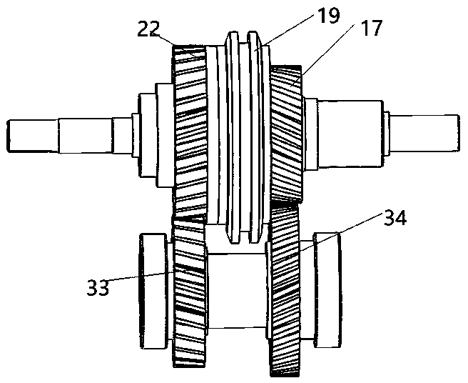
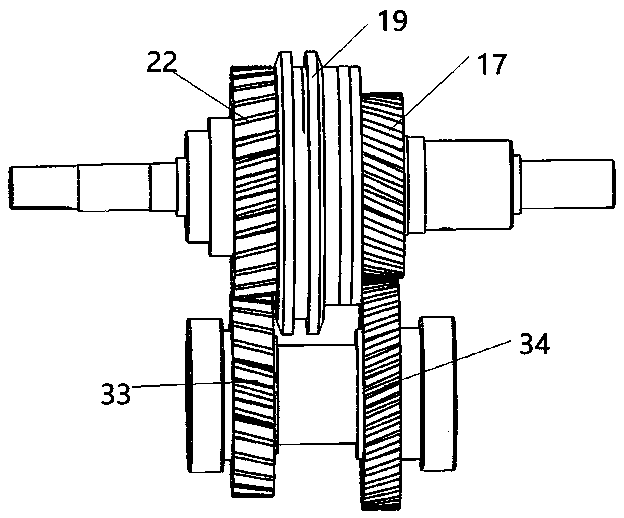
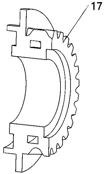
[0037] see figure 1 with figure 2 , an integrated motor reduction drive system for a helicopter empennage includes a disc motor and a two-speed transmission mechanism. The disc motor includes a stator 4 , a rotor 5 , a roller bearing 7 , a bearing bracket 9 and a middle box 2 , and the roller bearing 7 is sleeved on the bearing bracket 9 and coaxially located in the motor casing 3 with the rotor 5 . The two-speed transmission mechanism includes a gearbox body 1, an output shaft 28, a first-speed driving gear 17, a first-speed driven gear 34, a second-speed driving gear 22, a second-speed driven gear 33, an intermediate shaft 32 and a synchronizer 19. The output shaft 28 and the intermediate shaft 32 are located in the gearbox body 1 in parallel, the output end of the output shaft 28 is located outside the gearbox body 1, and the output shaft 28 on the side of the output end is fixedly installed in the gearbox body through the fourth roller bearing 27 1, the output end of th...


PUM


Abstract

The invention relates to an integrated motor speed reduction driving system for a helicopter empennage. The integrated motor speed reduction driving system comprises a disk type motor and a two-levelspeed change mechanism, wherein the disk type motor comprises a stator, a rotor, a roller bearing and a bearing bracket; the two-level speed change mechanism comprises a speed change box body, an output shaft, two gear pairs, a middle shaft and a synchronizer. The improvement is that: the integrated motor speed reduction driving system further comprises a split type middle transmission mechanism;the middle transmission mechanism comprises a rotary sleeve arranged on the output shaft in a sleeving manner, a rotary bracket, a first rotary body, a second rotary body, a third rotary body and thelike. The split type structure of the integrated motor speed reduction driving system reduces non-uniform stress on the output shaft, avoids the impact influence on the output shaft in a gear shiftingprocess, and guarantees stable operation of a helicopter tail rotor. A power end of the integrated motor speed reduction driving system for the helicopter empennage is directly output from a rotor end of the disk type motor, so that high integration of the integrated structure of a motor speed reducer is realized; the disk type motor is powered by an APU or a battery, so as to fulfill the aim ofelectrically driving a helicopter to be balanced or change the direction.

Description

technical field [0001] The invention belongs to the technical field of helicopters, and in particular relates to an integrated motor reducer system at the tail of an electrically driven helicopter. [0002] technical background [0003] The power source of the transmission system of the existing helicopter empennage is to share an engine with the main rotor of the helicopter, which is powered by the engine, and is formed through parts such as the main reducer, the tail drive shaft, the intermediate reducer, the tail reducer, the tail rotor pitch change pull rod, etc.; Among them, the tail drive shaft, the intermediate reducer, and the tail reducer transmit the energy from the main reducer to the tail rotor to drive the tail rotor to rotate; the pilot controls the pedal to drive the tail rotor pitch change rod through the control line, thereby changing the tail rotor blade. The angle of attack can be changed to change the thrust of the tail rotor to achieve the purpose of heli...

Claims


Application Information

Patent Timeline
Patent Type & Authority Patents(China)
IPC IPC(8): F16H1/20B64C27/12B64D27/24
CPCB64C27/12B64D27/24Y02T50/60
Inventor 甄圣超陈盼盼孙浩黄康李传阳周哲郭俊
Owner HEFEI UNIV OF TECH
Why Eureka
Try Eureka