Gas solution supply device and method executed by gas solution supply device

A supply device and gas supply technology, applied in the direction of gas/steam and liquid mixing, dissolution system, liquid degassing general layout, etc., can solve the difficulty of high concentration of ozone water, difficulty in suppressing the change of ozone water delivery pressure, difficulty in Increase the pressure of the gas-liquid separator and other problems to achieve the effect of suppressing the fluctuation of the delivery pressure

Pending Publication Date: 2022-04-05
EBARA CORP
View PDF1 Cites 0 Cited by
  • Summary
  • Abstract
  • Description
  • Claims
  • Application Information

AI Technical Summary

Problems solved by technology

[0007] However, in the conventional device, only one gas-liquid separator is provided, and a pump (a pump that sends ozone water to the point of use) is arranged at the rear stage of the gas-liquid separator. Therefore, it is difficult to improve the efficiency of the gas-liquid separator. Pressure, high concentration of ozone water is difficult
In addition, when the pump is an air-driven pump, it is difficult to suppress fluctuations in the delivery pressure of ozone water due to the influence of pump pulsation.

Method used


Image

  • Gas solution supply device and method executed by gas solution supply device
  • Gas solution supply device and method executed by gas solution supply device
  • Gas solution supply device and method executed by gas solution supply device

Examples


no. 1 approach

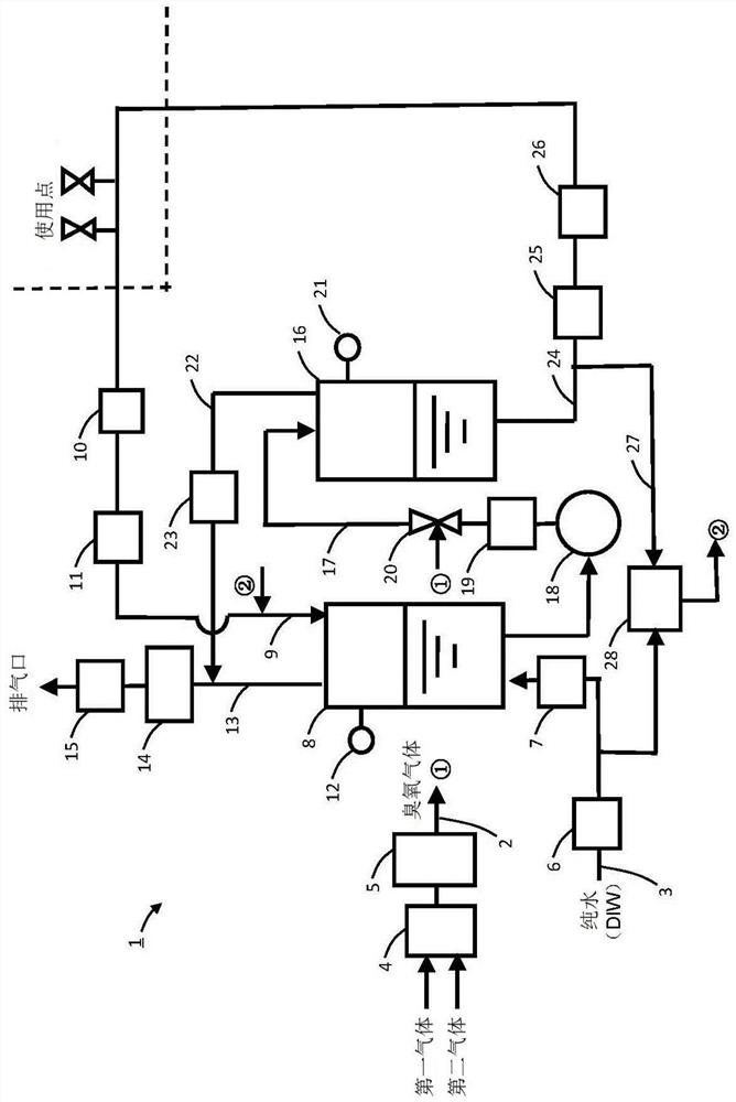
[0070] The structure of the ozone water supply apparatus which concerns on 1st Embodiment of this invention is demonstrated, referring drawings. figure 1 It is explanatory drawing which shows the structure of the ozone water supply apparatus of this embodiment. Such as figure 1 As shown, the ozone water supply device 1 includes a gas supply line 2 for supplying ozone gas as a raw material of ozone water, and a liquid supply line 3 for supplying pure water (DIW) as a raw material of ozone water.

[0071] A first gas (for example, oxygen gas) and a second gas (for example, carbon dioxide gas, nitrogen gas, or a mixed gas of carbon dioxide gas and nitrogen gas) serving as a raw material of ozone gas are supplied to the gas supply line 2 . A gas flow regulator 4 and an ozone generator 5 are provided on the gas supply line 2 . The gas flow regulator 4 adjusts the flow of the first gas and the second gas respectively. The ozone generator 5 generates ozone gas from the source gas ...

no. 2 approach

[0085] Next, an ozone water supply device 1 according to a second embodiment of the present invention will be described. Here, the difference between the ozone water supply apparatus 1 of 2nd Embodiment and 1st Embodiment is demonstrated centering. Here, unless otherwise mentioned, the structure and operation of this embodiment are the same as those of the first embodiment.

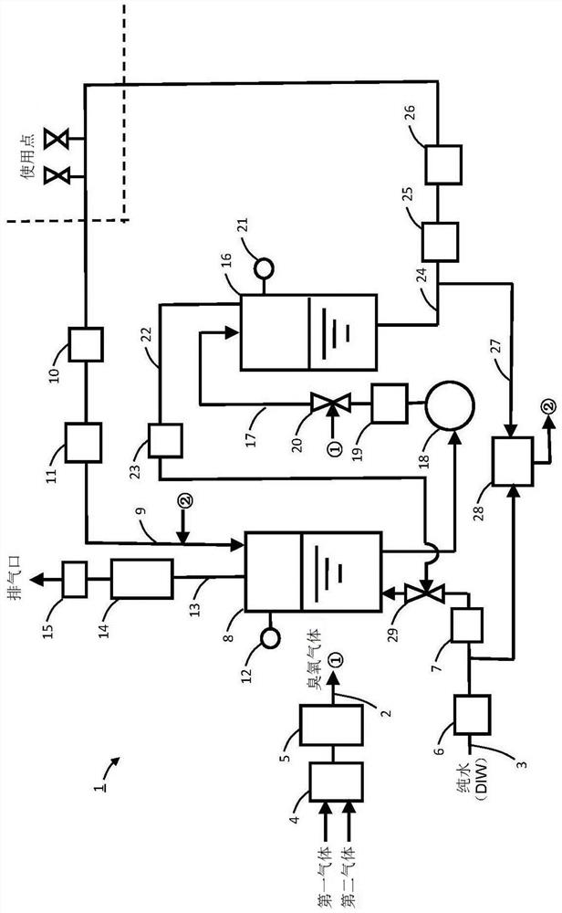
[0086] figure 2 It is explanatory drawing which shows the structure of the ozone water supply apparatus 1 of this embodiment. Such as figure 2 As shown, in this embodiment, the second gas dissolving nozzle 29 is provided on the liquid supply line 3 , and the discharge line 22 from the second gas-liquid separator 16 is connected to the second gas dissolving nozzle 29 . The second gas dissolving nozzle 29 dissolves undissolved excess ozone gas discharged from the second gas-liquid separator 16 in the pure water supplied to the liquid supply line 3 . Ozone water is supplied from the liquid supply line ...

no. 3 approach

[0091] Next, an ozone water supply device 1 according to a third embodiment of the present invention will be described. Here, the difference between the ozone water supply apparatus 1 of 3rd Embodiment and 2nd Embodiment is demonstrated centering. Here, unless otherwise mentioned, the structure and operation of this embodiment are the same as those of the second embodiment.

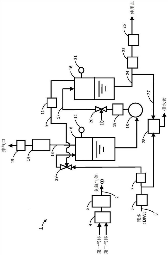
[0092] image 3It is explanatory drawing which shows the structure of the ozone water supply apparatus 1 of this embodiment. Such as image 3 As shown, in this embodiment, the circulation supply line 9 which circulates the ozone water which is not used at the point of use and supplies this ozone water to the 1st gas-liquid separator 8 is not provided. Therefore, compared with the first embodiment and the second embodiment, the pressure of the first gas-liquid separator 8 can be increased, and the concentration of ozone water can be made high.

[0093] In the ozone water supply device 1 of the present ...


PUM


Abstract

The invention provides a dissolved gas solution supply device and a method executed by the dissolved gas solution supply device, which can realize high concentration of the dissolved gas solution and can restrain fluctuation of sending pressure of the dissolved gas solution. A dissolved gas solution supply device (1) is provided with: a first gas-liquid separator (8) that stores a dissolved gas solution; a second gas-liquid separator (16) that is provided downstream of the first gas-liquid separator and stores a dissolved gas solution to be supplied to a point of use; and an intermediate line (17) that is provided between the first gas-liquid separator and the second gas-liquid separator. A booster pump (18) which is provided in the intermediate line and which raises the pressure of the gas-dissolved solution supplied from the first gas-liquid separator to the second gas-liquid separator; and a gas supply line (2) which supplies a gas that is a raw material for the gas-dissolved solution. And a gas dissolving unit (20) that is provided in the intermediate line and that dissolves the gas supplied from the gas supply line in the gas-dissolved liquid supplied from the first gas-liquid separator.

Description

technical field [0001] The present invention relates to a gas solution supply device for supplying a gas solution, and more particularly to a technique for increasing the concentration of a gas solution. Background technique [0002] Conventionally, ozone water has been used for cleaning electronic components such as semiconductor devices and liquid crystals. Ozone water is produced by dissolving ozone gas in ultrapure water, and is supplied to the point of use (semiconductor device factory, electronic component factory, etc.). [0003] In a conventional device for producing ozone water, for example, ozone water produced by dissolving ozone gas in ultrapure water is stored in a gas-liquid separator, and the gas is pumped from the gas by a pump installed in the rear stage (downstream side) of the gas-liquid separator. The liquid separator sends ozone water to the point of use (for example, refer to Patent Document 1). [0004] prior art literature [0005] patent documents...

Claims


Application Information

Patent Timeline
Patent Type & Authority Applications(China)
IPC IPC(8): B01F23/20B01F25/30
CPCB01F23/2326B01F23/237613B01F23/29B01F23/232B01F23/19B01F25/31243B01F25/53C01B13/11C02F2201/784C02F2201/782C02F1/78B01F23/23B01F21/30B01F23/23122B01F23/2366B01F35/71805B01F35/20B01F23/231141B01F2101/58B01F35/7176B01F23/803B01F23/703B01F35/718051B01F25/51B01F23/2323B01F25/31B01F35/2211B01D19/0063B01D19/0068H01L21/02041
Inventor 小泽卓荒木裕二渡边敏史中川洋一木村梨沙徐涛
Owner EBARA CORP
Why Eureka
Try Eureka