Pressure forming device and method

A forming device and forming method technology, applied in forging/pressing/hammer device, forging/pressing/hammering machinery, manufacturing tools, etc., can solve the problems of uneven texture of forming workpieces, long blank flow distance, difficult forming, etc. , to achieve the effects of balanced and stable force on the blank material tissue, low cost, and balanced blank material process

Active Publication Date: 2018-05-25
INNER MONGOLIA WENDING TECH CO LTD
View PDF6 Cites 0 Cited by
  • Summary
  • Abstract
  • Description
  • Claims
  • Application Information

AI Technical Summary

Problems solved by technology

[0011] In view of the above problems, an object of the present invention is to propose a pressure forming device that can solve the problems of difficulty in forming and uneven texture of the formed workpiece caused by the too far flow of the billet.

Method used


Image

  • Pressure forming device and method
  • Pressure forming device and method
  • Pressure forming device and method

Examples


Embodiment 1

[0054] In the description herein, it should be understood that the orientation or positional relationship indicated by the terms "upper", "lower", "inner", "outer", etc. is based on the orientation or positional relationship shown in the drawings, and is only for the convenience of description The present invention and simplified description do not indicate or imply that the device or element referred to must have a specific orientation, be constructed and operate in a specific orientation, and thus should not be construed as limiting the present invention.

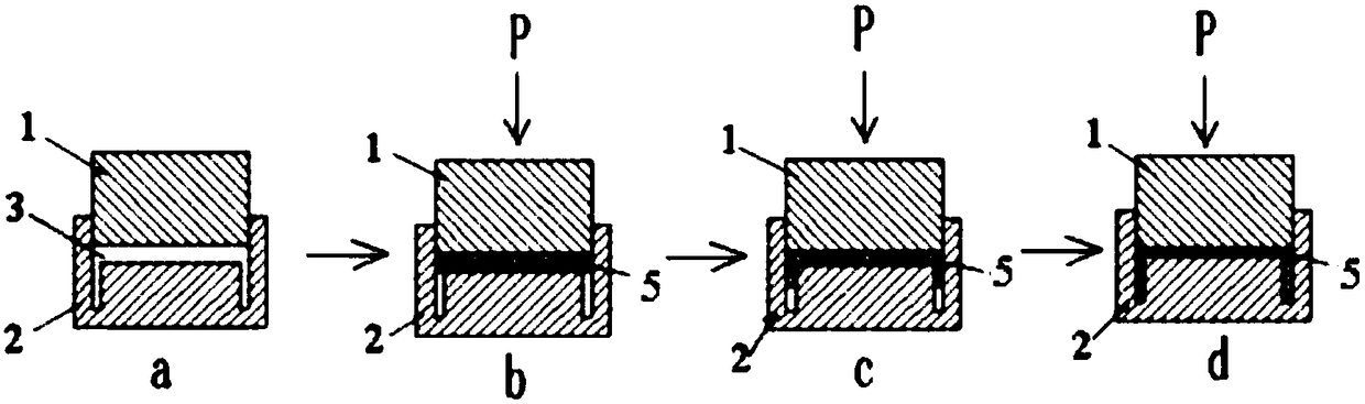
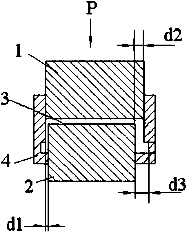
[0055] The preferred embodiment provides a pressure forming device which is mainly but not limited to be used as a swaging device. see figure 2 , the pressure forming device provided in this embodiment includes an upper mold 1, a lower mold 2 and a movable mold 4, the upper mold 1 and the lower mold 2 are relatively arranged and can move relatively, and the movable mold 4 is sleeved outside the upper mold 1 and the lower...

Embodiment 2

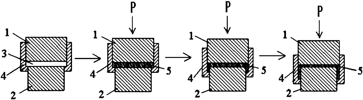
[0069] This preferred embodiment provides a pressure forming device, the structure of which is basically the same as the pressure forming device provided in the preferred embodiment 1, the difference is: please refer to Figure 4 and Figure 5 , all sub-lower molds 21 form solid cylinders or hollow cylinders during the pressure forming process. After the pressure forming is completed, driven by the power device, they first move radially outward to make the lower mold expand, and then move radially inward. In order to make the lower mold shrink. The power device that drives the sub-lower mold 21 to move radially is preferably but not limited to a hydraulic cylinder arranged in a direction parallel to the axis of the pressure forming device and connected to the output shaft of the hydraulic cylinder and converts the linear reciprocating motion output by the hydraulic cylinder into Transmission mechanism for radial movement.

[0070] This embodiment also provides a pressure for...

Embodiment 3

[0077] This preferred embodiment provides a pressure forming device, the structure of which is basically the same as the pressure forming device provided in the preferred embodiment 1, the difference is: please refer to Figure 6 and Figure 7 , the lower mold includes at least two fan-shaped sub-lower molds 21 and at least two wedge-shaped sub-lower molds 21, the fan-shaped sub-lower molds 21 and wedge-shaped sub-lower molds 21 are alternately arranged, and all sub-lower molds 21 forms a hollow cylinder during the pressure forming process. After the pressure forming is completed, the wedge-shaped sub-lower mold 21 and the fan-shaped sub-lower mold 21 are driven by the power device to move radially inward in order to make the lower mold shrink.

[0078] This embodiment also provides a pressure forming method based on the above pressure forming device, which is basically the same as the pressure forming method provided in Preferred Embodiment 1, except that:

[0079] The metho...


PUM


Abstract

The invention discloses a pressure forming device and method and belongs to the technical field of metal workpiece machining. The pressure forming device and method are designed for solving the problems that forming is difficult and the workpiece texture is nonuniform due to the fact that the blank flowing path is excessively long in an existing device and method. The pressure forming device comprises an upper die, a lower die and a movable die. The upper die and the lower die are arranged oppositely and can move oppositely; the movable die is inserted into the lower die and/or arranged outside the upper die and the lower die in a sleeving mode, and the movable die can move up and down relative to the upper die and the lower die; and a die cavity is defined by the upper die, the lower dieand the movable die jointly, and in the forming process, the movable die moves relative to the upper die and the lower die so as to dynamically increasing the size of the die cavity. According to thepressure forming device and the pressure forming method based on the pressure forming device, the size of the die cavity can be dynamically increased, the blank flowing path is short and balanced, flow lines are uniform and stable, and the workpiece texture is uniform.

Description

technical field [0001] The invention relates to the technical field of metal workpiece processing, in particular to a pressure forming device and a pressure forming method based on the pressure forming device. Background technique [0002] Die forging is a forging method in which the metal blank is plastically deformed in the mold and filled with the cavity under the action of external force to obtain forgings of the desired shape and size. In the die forging process, the billet undergoes obvious plastic deformation as a whole, and there is a large amount of plastic flow; the flowing billet fills the mold cavity, and after filling, the pressure is maintained to form the required shape. [0003] Most metals are die forged in a hot state, so die forging is also called hot die forging. Compared with free forging, die forging can forge forgings with more complex shapes and more accurate dimensions, and the production efficiency is relatively high. It can mass produce forgings w...

Claims


Application Information

Patent Timeline
Patent Type & Authority Applications(China)
IPC IPC(8): B21J5/02B21J13/02
Inventor 王利民
Owner INNER MONGOLIA WENDING TECH CO LTD
Why Eureka
Try Eureka