Novel parking lot system for electric vehicles

A technology for electric vehicles and parking lots, applied in the field of parking lot systems, can solve the problems of inability to quickly change batteries and charging operations of cars, high precision requirements, and motor occupation.

Inactive Publication Date: 2018-05-25
XIHUA UNIV
View PDF3 Cites 5 Cited by
  • Summary
  • Abstract
  • Description
  • Claims
  • Application Information

AI Technical Summary

Problems solved by technology

[0004] Patents related to lifting replacement methods, such as the battery replacement robot described in CN201280003179, include a battery plugging mechanism, a lifting mechanism, etc., and the lifting mechanism makes the battery plugging mechanism go up and down, but the problem that it cannot solve is: for the existing In the parking lot, the renovation cost is high, and a set of replacement system can only satisfy one car at the same time, and it is impossible to quickly change batteries and charge multiple cars in the parking lot; patents related to the side pull-out replacement method, such as CN201510809560 What is described is a side battery replacement device for electric vehicles, including a battery box installation unit, a lifting unit, a control unit, and a locking unit; There is no judgment on the amount of electricity, resulting in low intelligence and many manual operations; the existing patents related to the automatic parking system of the parking lot, such as the automatic parking system described in CN 201510021169, include: parking spaces, mobile charging Robot and robot management system, the charging robot includes the robot body, fire fighting unit, traveling mechanism, battery pack and control unit, etc.; this system can facilitate the charging of elec...

Method used


Image

  • Novel parking lot system for electric vehicles
  • Novel parking lot system for electric vehicles
  • Novel parking lot system for electric vehicles

Examples


Embodiment Construction

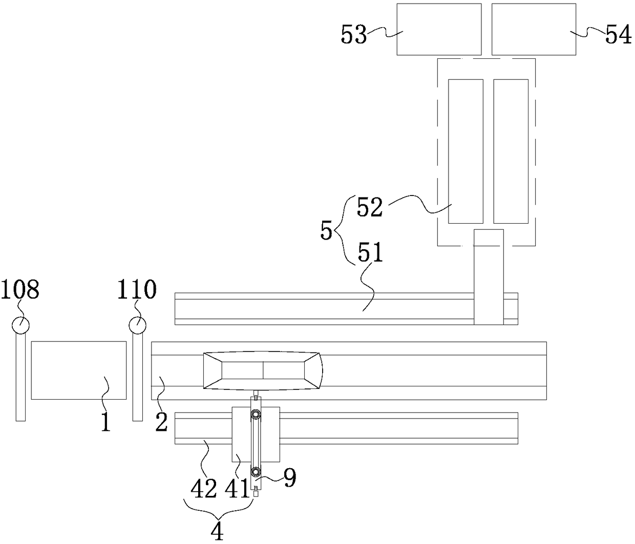
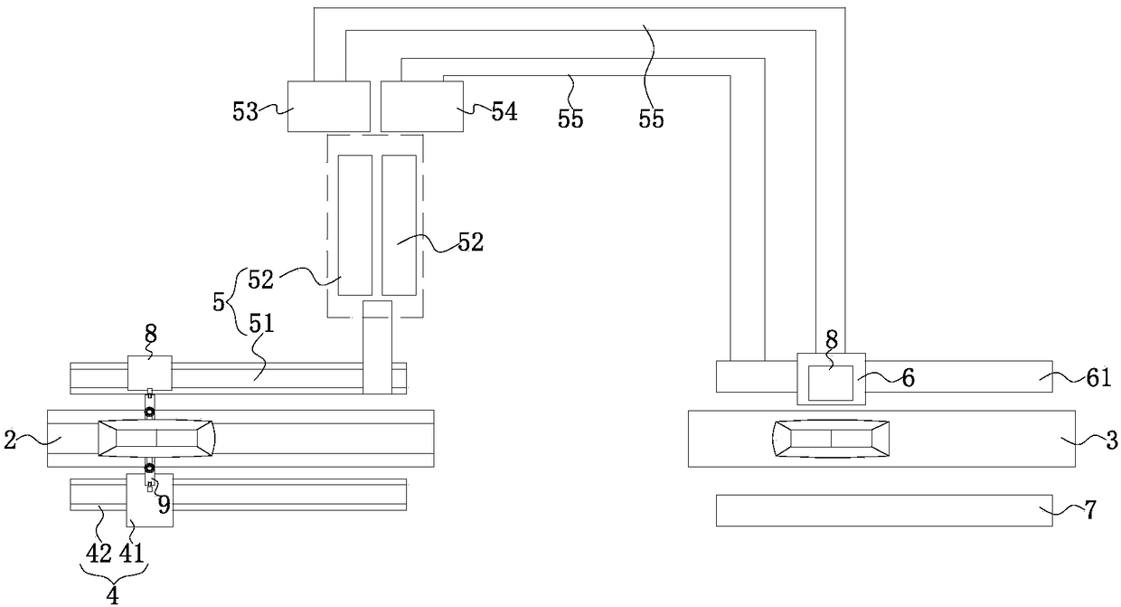
[0064] Such as Figure 1-Figure 16 A new type of parking lot system for electric vehicles is shown, the system is used to park the electric vehicle in which the battery module 8 is arranged in the central position of the chassis, and the corresponding position where the battery module 8 is placed on the electric vehicle is provided with a horizontal through groove, and the horizontal channel The battery module 8 placed in the through groove can be pushed out from any side of the electric vehicle under the action of external force or with the assistance of corresponding pushing equipment on the vehicle; A wireless charging receiver 81 is arranged inside the side;

[0065] The battery module 8 can also be arranged in the front engine compartment or the rear luggage compartment of the electric vehicle; correspondingly, a transverse groove is respectively arranged at the front and rear of the chassis of the electric vehicle, and the bottom edge of the transverse groove is arranged...


PUM


Abstract

The invention particularly relates to a novel parking lot system for electric vehicles, wherein the novel parking lot system is high in intelligence degree and saves space. The system includes a firsttransmission platform and a second transmission platform which are placed in sequence. A robot mounting device is arranged on one side of the second transmission platform, and a battery recovery device is arranged on the other side of the second transmission platform. A third transmission platform is arranged at the position of an exit of a parking lot, and a battery push platform is arranged onone side of the third transmission platform; the robot mounting device includes a positioning and pushing platform, the positioning and pushing platform includes an elevating platform, and a guide rail type mobile platform that can move in the longitudinal and transverse directions of a first auxiliary conveyor belt is arranged on the elevating platform, a push mechanism is fixedly placed on the mobile platform, and the push mechanism can push out a walking robot placed on the mobile platform. An omni-wheel travelling mechanism can effectively improve the flexibility of automobile steering, reduce the parking space distance of the parking lot, and improve the utilization rate of the site.

Description

technical field [0001] The invention relates to the technical field of electric vehicles, in particular to a novel parking system for electric vehicles. Background technique [0002] Electric vehicles drive vehicles through the electric energy stored in batteries, which reduces the use of fossil energy by vehicles and is an important means to solve national energy problems. Due to the limitation of the current battery energy density, at the current level of battery technology development, battery charging usually takes several hours to complete, and the battery charging cannot be completed in a short time, and the battery charging with a large current will have a negative impact on the battery life. In addition, the current parking lot is mainly stored flat, occupying a large area of ​​land, so the number of storage is limited, it is difficult for car owners to find a parking space, and there is no protection for the car in the parking space; difficulty. [0003] The curre...

Claims


Application Information

Patent Timeline
IPC IPC(8): B60S5/06B60L11/18B62D63/02E04H6/08H04L29/08
CPCB60L53/80B60S5/06B62D63/02E04H6/08H04L67/12Y02T10/70Y02T10/7072
Inventor 陈子龙
Owner XIHUA UNIV
Why Eureka
Try Eureka