Upper rotor left and right swing control mechanism on rotorcraft

A technology of left-right swing and control mechanism, applied in the field of rotorcraft in aviation technology, can solve the problems of complex structure and inflexible control, and achieve the effect of flexible control, convenient control and improved steering flexibility.

Active Publication Date: 2017-08-01
河北天启通宇航空器材科技发展有限公司
View PDF5 Cites 2 Cited by
  • Summary
  • Abstract
  • Description
  • Claims
  • Application Information

AI Technical Summary

Problems solved by technology

[0006] The purpose of the present invention is to provide a left and right swing control mechanism of the upper rotor of the rotorcraft to solve the technical problems of complex structure and inflexible control in the prior art.

Method used


Image

  • Upper rotor left and right swing control mechanism on rotorcraft

Examples


Embodiment Construction

[0023] In order to make the purpose, technical solution and advantages of the present invention clearer, the technical solution of the present invention will be described in detail below. Apparently, the described embodiments are only some of the embodiments of the present invention, but not all of them. Based on the embodiments of the present invention, all other implementations obtained by persons of ordinary skill in the art without making creative efforts fall within the protection scope of the present invention.

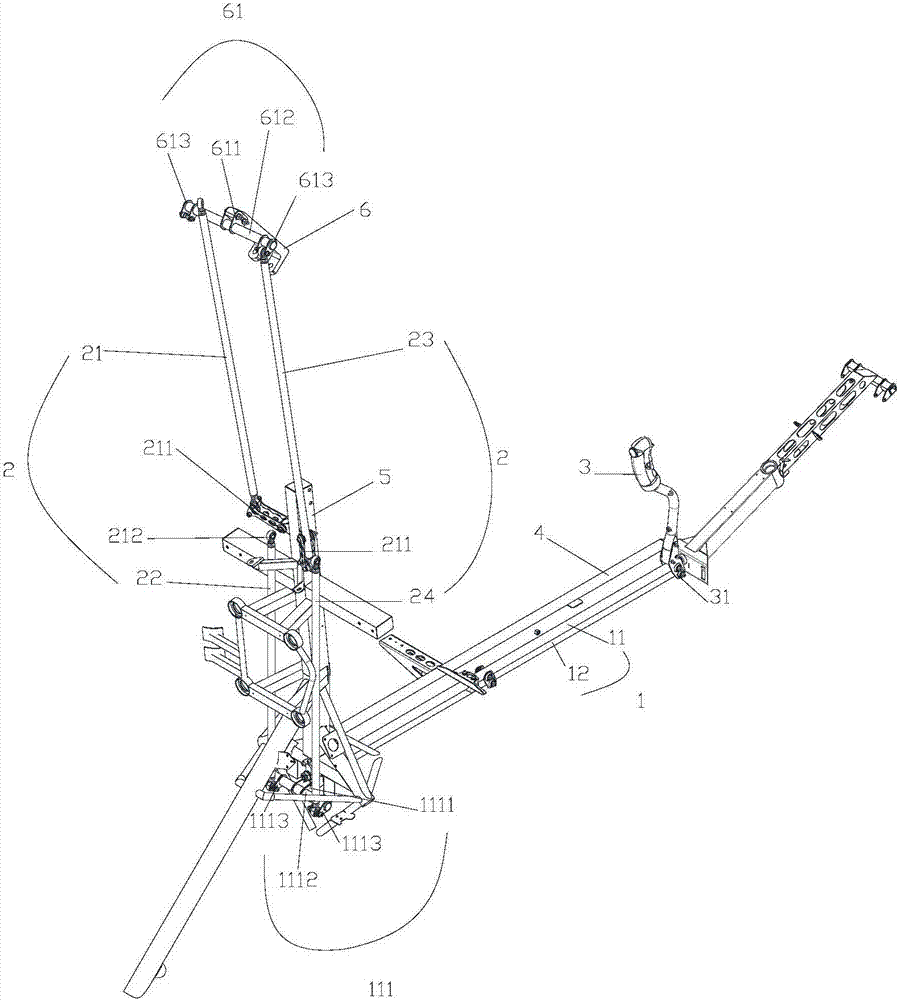
[0024] like figure 1 As shown, the present invention provides a left and right swing control mechanism for the upper rotor of a rotorcraft, including a control handle 3, a driving link 1, a driven link 2, a fixing clip 6, a fixing crossbeam 4 and a fixing column 5; wherein the control handle 3 is set It is used in the control cabin for the driver to control the flight direction of the rotorcraft; both the active link 1 and the driven link 2 are made of steel pi...


PUM


Abstract

The invention provides an upper rotor left and right swing control mechanism on a rotorcraft. The upper rotor left and right swing control mechanism comprises a control handle, a drive connecting rod, a driven connecting rod and a fixing clamp; the control handle is arranged in a control cabin for a driver to control the flight direction of the rotorcraft; the two ends of the drive connecting rod are movably connected with the control handle and the driven connecting rod correspondingly, and the control handle can be pulled forwards and backwards or rotate left and right to control the drive connecting rod to move along the control handle; one end, away from the drive connecting rod, of the driven connecting rod is movably connected with an upper motor through the fixing clamp, and the drive connecting rod moves forwards and backwards or rotates left and right to drive the driven connecting rod to rise or fall or tilt left and right, so that the tilt direction of the upper rotor is changed; and the upper rotor is movably connected with the fixing clamp, and the upper rotor can be driven by the driven connecting rod to swing up and down or left and right relative to the fixing clamp. The upper rotor left and right swing control mechanism on the rotorcraft has the characteristics of simple structure and flexible and convenient control.

Description

technical field [0001] The invention relates to the technical field of rotorcraft in aviation technology, in particular to a left and right swing control mechanism of the upper rotor of the rotorcraft. Background technique [0002] Gyroplane is a very light aircraft between helicopter and airplane (the maximum take-off weight is 560KG), its forward force is directly provided by the propeller driven by the engine. The upper rotor of the rotorcraft is not connected with the engine transmission system. The engine does not drive the upper rotor to provide lift for the aircraft, but during the flight of the rotorcraft, the upper rotor is blown by the front airflow to rotate to generate lift, like a windmill; the rotor The system is driven by its own power only at startup, which is called prerotate, and is driven by air force after takeoff. [0003] When the gyroplane is flying, the ascending, descending and turning power are mainly generated by the upper rotor, and the driver co...

Claims


Application Information

Patent Timeline
Patent Type & Authority Applications(China)
IPC IPC(8): B64C27/32B64C27/02B64C9/00
CPCB64C9/00B64C27/02B64C27/32
Inventor 宋梓涵
Owner 河北天启通宇航空器材科技发展有限公司
Why Eureka
Try Eureka