
Manufacturing and installing process for rescue counterweight flash ball

An installation process and technology of flashing balls, which are applied in the direction of electric light sources, lighting devices, portable lighting devices, etc., can solve problems such as inability to guarantee product quality requirements and product functions, and single production and manufacturing.

Inactive Publication Date: 2018-05-25
QINGDAO CENTURY YUNFAN IND
View PDF0 Cites 0 Cited by
  • Summary
  • Abstract
  • Description
  • Claims
  • Application Information

AI Technical Summary

Problems solved by technology

[0002] Each product has its unique production and processing methods, and the different structures and materials of the product will also have a very different installation process from other products. According to the characteristics of the product, a more complete and most suitable production and installation process can be formulated to make the product There are fewer detours in the production and installation process, and at the same time, it can save manpower, material resources and raw materials, and produce high-quality and low-cost products safely and quickly. The rescue counterweight flash ball is a non-standard product, so the production of the product is single. This determines that the production and manufacture of components must have its own special manufacturing process, otherwise the quality requirements and functions of the product cannot be guaranteed

Method used


Image

  • Manufacturing and installing process for rescue counterweight flash ball

Examples


Embodiment Construction

[0008] The present invention will be further described below in conjunction with accompanying drawing.

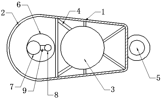
[0009] Taking the rescue counterweight flashing ball as an example, ABS plastic is used to inject into the mold on the injection molding machine to form a shell 1 with fixed ribs 4 fixed counterweight ball 3 embedded in it and a tether ring 5 embedded in the outer shell 1—use colorless plastic raw materials in the mold. Inject the transparent top shell 2 into the mold of the injection molding machine—deburr and polish the outer surface of the shell 1 and top shell 2—process the matching external thread and internal thread on the shell 1 and top shell 2—put the luminous tube 7 on the assembly line , battery 8, and mercury contact intermittent switch 9 are assembled into illuminant 6—put illuminant 6 into top case 2, and the inner thread of top case 2 is screwed against the outer thread of outer case 1 for tight assembly—overall inspection—functional test: Tie the end of the ...


PUM


Abstract

The invention discloses a manufacturing and installing process for a rescue counterweight flash ball. The manufacturing and installing process comprises the following steps that ABS is used for perform injection molding to form a fixed counter weight ball 3 internally embedded with fixing ribs 4 and an outer shell 1 with a tying rope ring 5 embedded outside; a transparent top shell 2 is formed byinjection molding of a colorless plastic raw material; the outer shell 1 and the top shell 2 is subjected to deburring and polishing; external threads is machined on outer shell 1, and internal threads is machined on the top shell 2; a light-emitting tube 7, a battery 8, a mercury contact intermittent switch 9 are assembled into a light-emitting body 6 on an assembling line; the light-emitting body 6 is installed in the top shell 2, and the inner threads of the top shell 2 are screwed and assembled tightly to the outer threads of the outer shell 1; whole inspection is carried out; and a function test is carried out. According to the manufacturing and installing process for the rescue counterweight flash ball, orderly production and installation can be carried out according to specifications, so that the manufacturing quality and requirements of products are guaranteed, irrelevant and unnecessary links are reduced, meanwhile, raw materials can be saved, cost can be reduced, and the machining and installing process follows rules, and is safe and orderly.

Description

technical field [0001] The invention relates to a process of making a rescue rope throwing and guiding a luminous ball at night, that is, a manufacturing and installation process of a rescue counterweight flashing ball. Background technique [0002] Each product has its unique production and processing methods, and the different structures and materials of the product will also have a very different installation process from other products. According to the characteristics of the product, a more complete and most suitable production and installation process can be made. There are fewer detours in the production and installation process, and at the same time, it can save manpower, material resources and raw materials, and produce high-quality and low-cost products safely and quickly. The rescue counterweight flash ball is a non-standard product, so the production of the product is single. This determines that the production and manufacture of components must have its special ...

Claims


Application Information

Patent Timeline
IPC IPC(8): F21L4/00F21V23/04F21V15/01B29C45/14
CPCF21L4/00B29C45/14F21V15/01F21V23/04
Inventor 赵岳鹏
Owner QINGDAO CENTURY YUNFAN IND
Learn More