Direct-type backlight module and liquid crystal displayer
A backlight module and direct-type technology, applied in the direction of instruments, optics, nonlinear optics, etc., can solve the problems of increased design cost, long mold cycle, increased product design cycle and design cost, and achieve the effect of reducing manufacturing cost
- Summary
- Abstract
- Description
- Claims
- Application Information
AI Technical Summary
Problems solved by technology
Method used
Image

Examples
no. 1 example
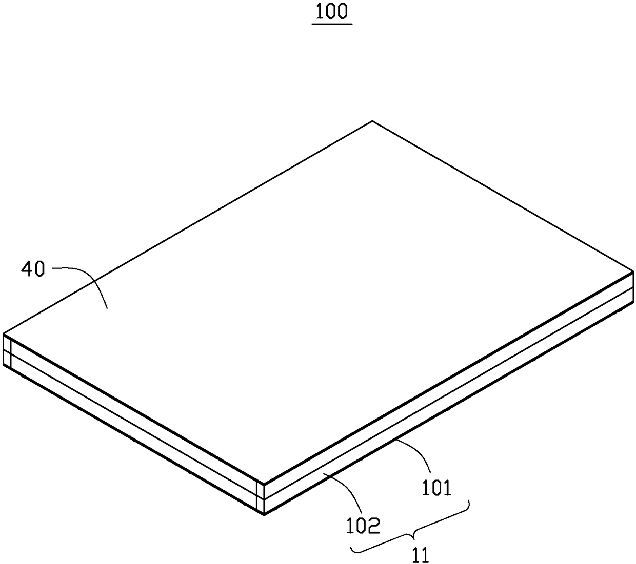
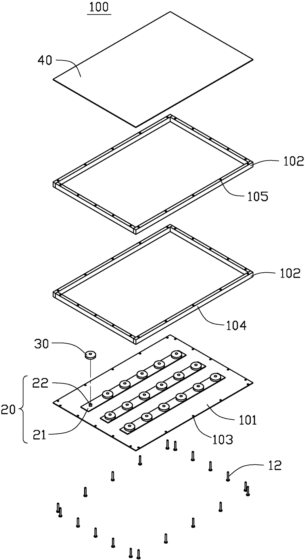
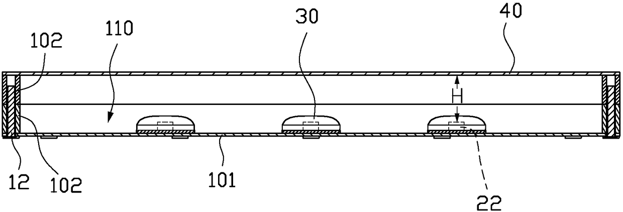
[0019] see Figure 1-5 , is a direct type backlight module 100 provided by the present invention, which includes: a backplane 10 , a light source 20 , a secondary optical lens 30 and an optical film 40 .
[0020] The backplane 10 includes a substrate 101 and at least two backplane frames 102 . The substrate 101 and the backplane frame 102 are formed separately. The substrate 101 and the backplane frame 102 are made of metal or plastic. Each of the backplane frames 102 includes four connected plate-shaped side edges 104 , and two adjacent side edges 104 are perpendicular to each other. The at least two backplane frames 102 are detachably assembled to form a height-adjustable backplane side frame 11 , and the base plate 101 is fixed to one end surface of the backplane side frame 11 to form an accommodating cavity 12 . The substrate 101 is fixed to one end surface of the backplane side frame 11 by screws or glue.
[0021] The at least two backplane frames 102 are fixed by any...
no. 2 example
[0030] see Figure 6 The structure of the direct-type backlight module 200 provided in this embodiment is basically the same as that of the direct-type backlight module 100 in the first embodiment, except that the screws are only used to fix the substrate 101 and the backlight adjacent to the substrate 101. The board frame 102 and every two back board frames 202 are fixed together by snap-fitting. Specifically, a protrusion 220 is provided on the side edge 204 of one of the backplane frames 202, and a card slot 210 matched with the protrusion 206 is arranged on the side edge 204 of the other backplane frame 102. The protrusion 220 may be a plurality of separated columns, or may be an annular protrusion surrounding the accommodating cavity.
no. 3 example
[0032] see Figure 7 The structure of the direct-type backlight module 300 provided in this embodiment is basically the same as that of the direct-type backlight module 100 in the first embodiment, the difference is that the screws are only used to fix the substrate 101 and the backplane adjacent to the substrate 101 frame 102 , and every two backplane frames 302 are fixed together by magnets 301 . Specifically, grooves are respectively provided on each backplane frame 302 , and a magnet 301 is fixed in the groove, so that the magnets 301 attract each other to fix the two backplane frames 302 .
[0033] In a word, all implementations that can fix and stack the backplane frame 102 can be used in the present invention, which will not be repeated here.
PUM
 Abstract
Description
Claims
Application Information
 - R&D
- Intellectual Property
- Life Sciences
- Materials
- Tech Scout
- Unparalleled Data Quality
- Higher Quality Content
- 60% Fewer Hallucinations
Browse by: Latest US Patents, China's latest patents, Technical Efficacy Thesaurus, Application Domain, Technology Topic, Popular Technical Reports.
© 2025 PatSnap. All rights reserved.Legal|Privacy policy|Modern Slavery Act Transparency Statement|Sitemap|About US| Contact US: help@patsnap.com