Optical unit

A technology of optical units and optical components, applied in the direction of optical components, optical, electrical components, etc., can solve the problem of being unable to suppress the shaking of optical modules, achieve the effects of suppressing tilt, suppressing shaking, and reducing the risk of damage

Active Publication Date: 2018-05-25
SANKYO SEIKI MFG CO LTD
View PDF5 Cites 15 Cited by
  • Summary
  • Abstract
  • Description
  • Claims
  • Application Information

AI Technical Summary

Problems solved by technology

Although the above-mentioned support structure is not a cantilever structure, there is a risk that the optical module will tilt around the pivot part, and there is a risk that the shaking of the optical module will not be suppressed

Method used


Image

  • Optical unit
  • Optical unit
  • Optical unit

Examples


Embodiment Construction

[0034] (the whole frame)

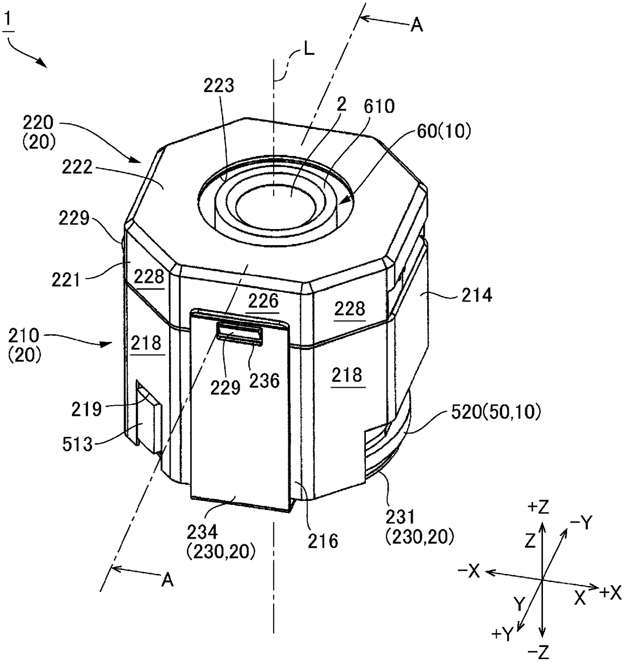
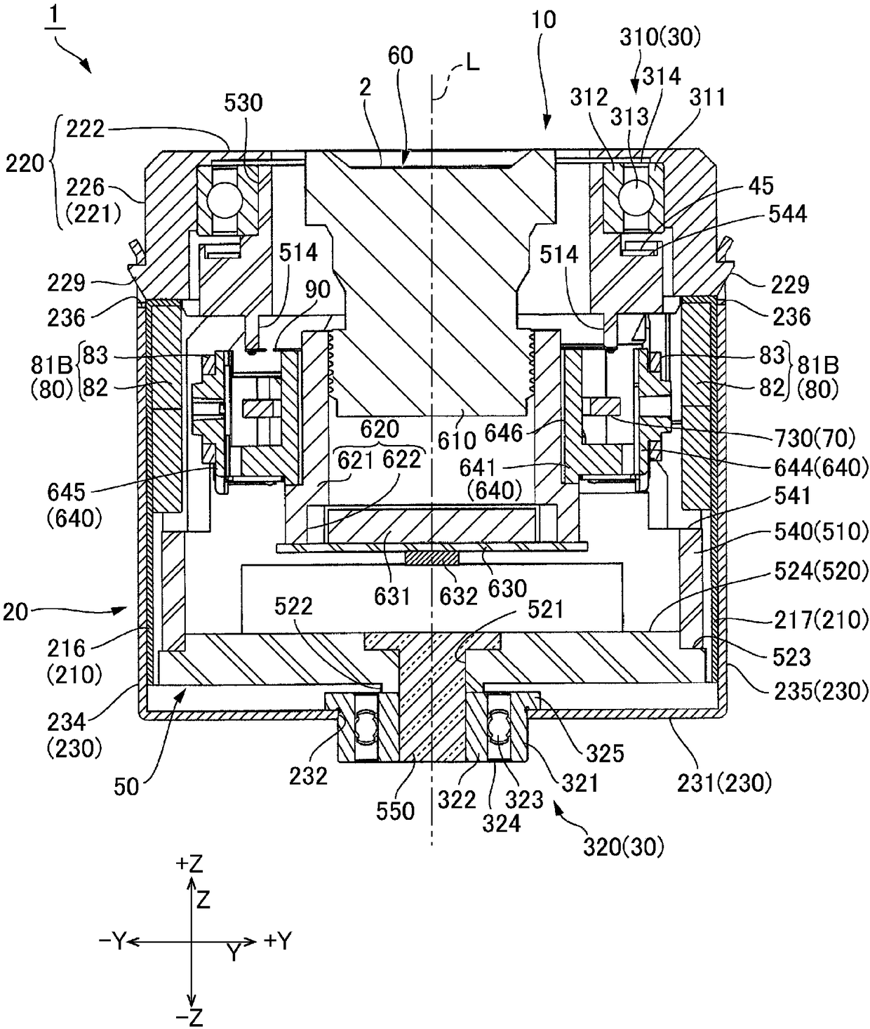
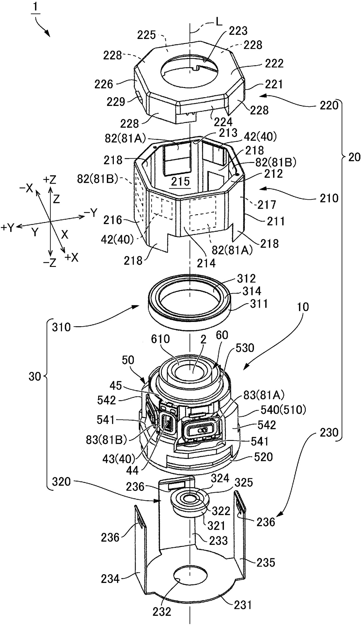
[0035] Hereinafter, an embodiment of an optical unit 1 including an optical module to which the present invention is applied will be described with reference to the drawings. In this specification, the three axes of XYZ are directions perpendicular to each other. One side of the X-axis direction is represented by +X, the other side is represented by -X, one side of the Y-axis direction is represented by +Y, and the other side is represented by -Y indicates that one side of the Z-axis direction is indicated by +Z, and the other side is indicated by -Z. The Z axis direction is consistent with the optical axis direction L of the optical module. In addition, the −Z direction is the image side in the optical axis direction L, and the +Z direction is the subject side in the optical axis direction L. In this specification, the X-axis direction is referred to as a first direction, and the Y-axis direction is referred to as a second direction. In addition,...


PUM


Abstract

An optical unit capable of reducing wobbling of an optical module that rotates about an optical axis while rotating, and reducing the risk that the rotary bearing portion is damaged by impact is disclosed. The optical unit (1) includes a subject-side rotary bearing part (310) located on a subject side of an optical module (60) and an image-side rotary bearing part (320) located on an image side ofthe optical module. The two rotary bearing parts disposed on both the subject side and the image side of the optical module (60) make it possible to restrain the tilt of the optical module (60) and restrain backlash during a rotation of the optical module (60) around an optical axis. This prevents the optical module (60) from becoming a cantilever state and a twisting load from being applied dueto an impact. Thus, it is possible to reduce the possibility of breakage of the rotary bearing parts due to an impact. A movable body (10) includes a rotary bearing holder (50) which swingably supports the optical module. A rolling magnetic-drive mechanism (40) is disposed between the rotary bearing holder (50) and a fixed body.

Description

technical field [0001] The present invention relates to an optical unit that performs roll correction by rotating an optical module including an optical element around an optical axis. Background technique [0002] Among optical units installed in a mobile terminal or a mobile body, there is an optical unit that includes a mechanism for correcting shake by swinging or rotating an optical element in order to suppress disorder of captured images when the mobile terminal or mobile body moves. mechanism. For example, the optical unit of Patent Document 1 includes a swing mechanism (magnet drive mechanism for swing) corresponding to shaking in two directions of pitch / tilting and yaw / panning. The module swings in the pitch direction and the yaw direction. In addition, corresponding to the rotation of the optical element around the optical axis, the optical unit includes a roll correction mechanism (magnetic drive mechanism for roll) that rotates the movable member including the ...

Claims


Application Information

Patent Timeline
Patent Type & Authority Applications(China)
IPC IPC(8): G03B5/00G02B27/64
CPCG02B27/646G03B5/00G02B7/021G02B7/08H02K33/12
Inventor 南泽伸司须江猛
Owner SANKYO SEIKI MFG CO LTD
Why Eureka
Try Eureka