Refrigeration structure for heat dissipation pipe

A duct and left heat dissipation technology, applied in the field of pipes, can solve the problems of single heat dissipation function, poor effect, and poor heat dissipation effect of heat dissipation pipes, and achieve the effect of rapid temperature control and accelerated heat dissipation.

Inactive Publication Date: 2018-05-25
成都西华升腾科技有限公司
View PDF5 Cites 1 Cited by
  • Summary
  • Abstract
  • Description
  • Claims
  • Application Information

AI Technical Summary

Problems solved by technology

[0006] The technical problem to be solved by the present invention is that the heat dissipation function adopted by the current chip is single, the heat dissipation effect of the heat dissipation pipe is poor, and only one side can be fanned for a long time, and the effect is very poor. The purpose is to provide a cooling structure for the heat dissipation pipe to solve above question

Method used


Image

  • Refrigeration structure for heat dissipation pipe

Examples


Embodiment

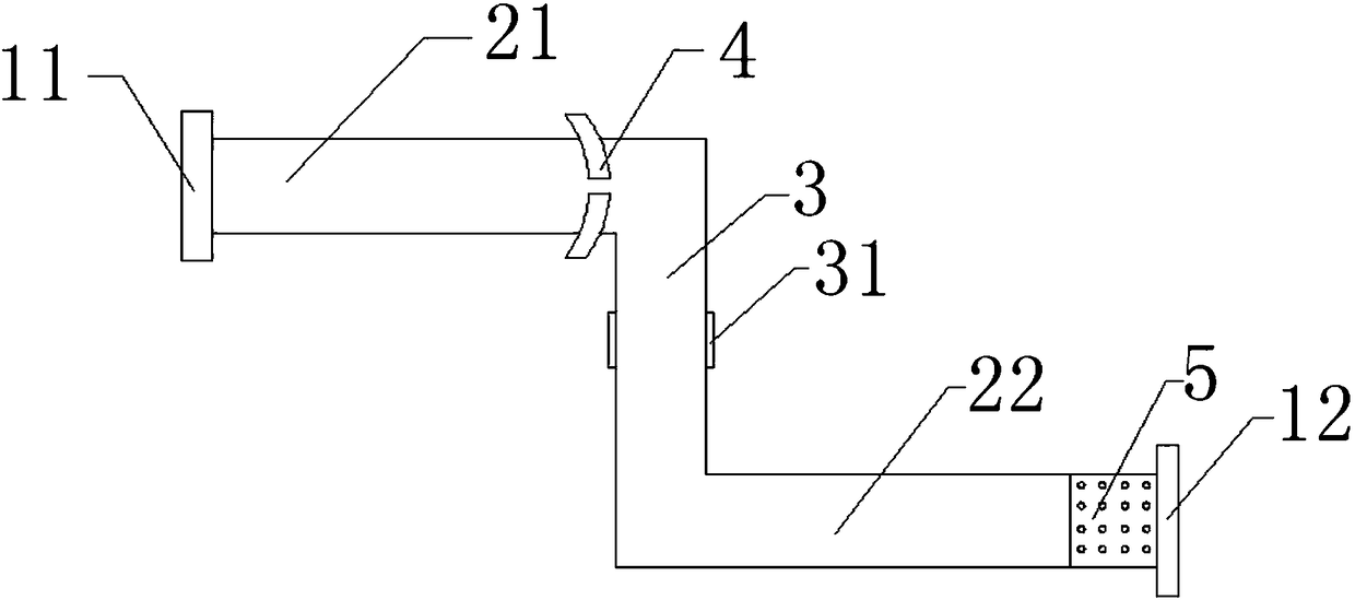
[0021] Such as figure 1 As shown, the present invention is used for the refrigeration structure of the heat dissipation pipe, the refrigeration structure for the heat dissipation pipe, the heat dissipation fan 1 and the heat dissipation pipe 2 arranged in the host, and it is characterized in that the middle part of the heat dissipation pipe 2 is provided with a turning angle 3, and the The two ends of the turning angle 3 are respectively connected with the left heat dissipation pipe 21 and the right heat dissipation pipe 22. The heat dissipation fan 1 includes a chip heat dissipation fan 11 and a refrigeration fan 12. The chip heat dissipation fan 11 is connected with the left heat dissipation pipe 21, and the refrigeration fan 12 is connected with the The right heat dissipation pipe 22 is connected, and the chip heat dissipation fan 11 and the refrigeration fan 12 supply air to the heat dissipation pipe 2 at the same time. The refrigerating fan 12 is provided with a refrigera...


PUM


Abstract

The invention discloses a refrigeration structure for a heat dissipation pipe, and the structure comprises a cooling fan and the heat dissipation pipe. The structure is characterized in that the central part of the heat dissipation pipe is provided with a turning corner; two ends of the turning corner are respectively connected with the left heat dissipation pipe and the right heat dissipation pipe; the cooling fan comprises a chip cooling fan and a refrigeration fan; the chip cooling fan is connected with the left heat dissipation pipe, and the refrigeration fan is connected with the right heat dissipation pipe; the chip cooling fan and the refrigeration fan supply air to the interior of the heat dissipation pipe at the same time. The heat dissipation pipe is used for control, and the chip cooling fan and the refrigeration fan supply air to the interior of the heat dissipation pipe at the same time, so the structure can form air turbulence in the heat dissipation pipe, and mixes coldair and hot air. The setting of the turning corner enables the temperature of the right heat dissipation pipe to be lower than the temperature of the left heat dissipation pipe. Through the integrateddesign, the structure can enable the heat of the left heat dissipation pipe to be transmitted to the interior of the right heat dissipation pipe for heat dissipation. Moreover, the right heat dissipation pipe is close to the outside, so the structure is better in refrigeration effect, is quicker in heat dissipation, and can achieve the quick heat dissipation.

Description

technical field [0001] The invention relates to a pipe, in particular to a cooling structure for a heat dissipation pipe. Background technique [0002] With the rapid development of chip technology in today's world, the performance of chips is changing with each passing day, and the size is getting smaller and smaller. At the same time, the heat dissipation problem in chip packaging has become an important factor restricting the improvement of chip performance. [0003] Flip Chip plays an important role in today's chip packaging. Flip-Chip packaging technology has many obvious advantages compared with traditional wire bonding processes, including superior electrical and thermal performance, high I / O pin count, package size decrease etc. [0004] In order to move towards higher performance, chip packaging has adopted the FC packaging method on a large scale, and the shorter contact connection brings smaller parasitic capacitance, and at the same time brings smaller packaging...

Claims


Application Information

Patent Timeline
Patent Type & Authority Applications(China)
IPC IPC(8): H01L23/367H01L23/467
CPCH01L23/3672H01L23/467
Inventor 谢义刚
Owner 成都西华升腾科技有限公司
Why Eureka
Try Eureka