
Flue gas and water same-channel dust-removing device

A technology of dust removal device and water outlet device, applied in the direction of using liquid separation agent, gas treatment, membrane technology, etc., can solve the problems of insufficient spray water line density, reduced dust removal effect, poor smoke exhaust, etc., to achieve the best dust removal effect, Improve the dust removal effect, increase the effect of contact area and time

Pending Publication Date: 2018-05-29
沈联峰
View PDF0 Cites 0 Cited by
  • Summary
  • Abstract
  • Description
  • Claims
  • Application Information

AI Technical Summary

Problems solved by technology

The density of the spray water line produced by the former is not enough, and it cannot be in full and long-term contact with the flue gas, and it is difficult to achieve an effective dust removal effect. Moreover, due to the limited area of ​​the flue, the number of vertical or parabolic water lines produced is limited, which cannot be applied in practice. Production
The latter is expensive, and the contact time between the generated water mist and the smoke is short, and it will affect the discharge of the smoke
In addition, these two methods consume a lot of water, and when the sprayed water flows down along the side wall of the flue, it will accelerate the air flow in the middle part of the flue and accelerate the discharge, which will further reduce the dust removal effect; An inverted V-shaped water film is formed on the inner wall of the flue, causing poor smoke exhaust or blocking the flue

Method used


Image

  • Flue gas and water same-channel dust-removing device
  • Flue gas and water same-channel dust-removing device
  • Flue gas and water same-channel dust-removing device

Examples


Embodiment Construction

[0024] The content of the present invention will be specifically described below in conjunction with the accompanying drawings and embodiments. However, the examples described below are for better elaboration of this patent, and are not intended to limit the protection scope of this patent.

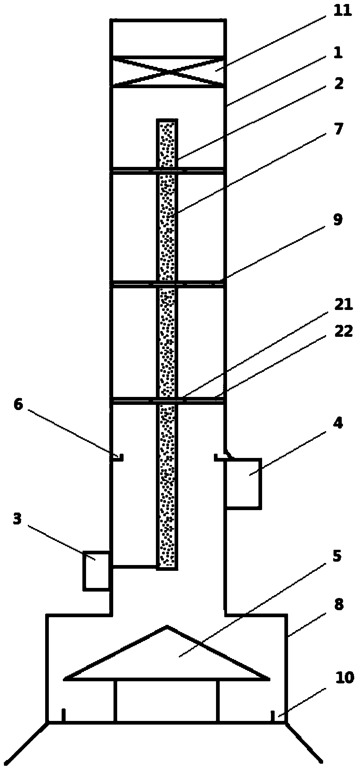
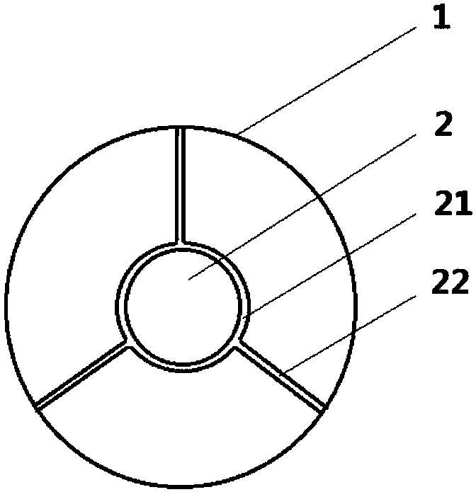
[0025] Such as figure 1 As shown, the smoke and water co-channel dedusting device includes a chimney, a water channel, a water inlet device, a water outlet device and a conical drainage cover. Wherein, the inner wall of the chimney is made of metal pipe or metal material, and one or more water channels are longitudinally arranged inside the chimney. The water channel is a tubular structure, and one, two, three or more water channels can be set according to the inner diameter of the chimney. When there are multiple water channels, the multiple water channels are located at the center of the chimney.

[0026] The pipe wall of the water channel is provided with a plurality of horizontal w...


PUM


Abstract

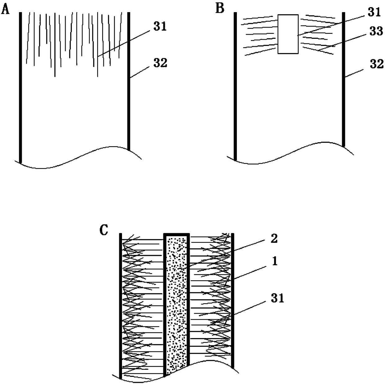
The invention discloses a flue gas and water same-channel dust-removing device. The flue gas and water same-channel dust-removing device comprises a chimney, a water channel, a water inlet device, a water outlet device and a conical water discharging cover; the inner wall of the chimney is a metal pipeline; the water channel is formed in the chimney longitudinally; a plurality of water spraying holes are formed in the pipe wall of the water channel; a water inlet of the water channel is connected with a water outlet of the water inlet device; the water outlet device is arranged on the chimney;the water outlet device comprises an annular water receiving tank and a water outlet channel; the conical water discharging cover is positioned at the bottom of the chimney. According to the device,tens of thousands of, or even millions of water lines can be sprayed in the chimney transversely at the same time on the basis of not influencing smoke discharging as much as possible, and each waterline can be rebounded after colliding to the inner wall of the chimney and can be dispersed into a plurality of smaller water lines to form a multi-directional spraying three-dimensional dust-removingnetwork, so that the contact area and the time of the water and the flue gas are greatly enlarged and prolonged, and the dust-removing effect is improved.

Description

technical field [0001] The invention belongs to the field of smoke and dust removal, and in particular relates to a smoke and water co-channel dust removal device for chimneys. Background technique [0002] Industrial dust usually refers to dusty industrial waste gas, or mechanical processes such as crushing, screening, conveying, and blasting in the processing of solid materials, or tiny dust generated in processes such as combustion, high-temperature melting, and chemical reactions. Among them, the dust of industrial waste gas contains dust with large particle size and the same chemical composition as the original solid substance, while the latter contains dust with small particle size and different chemical properties from the substance that generates it. The generation of particulate matter can be reduced by improving the production process and combustion technology. [0003] These industrial waste gases, which are often discharged in the process of industrial production...

Claims


Application Information

Patent Timeline
IPC IPC(8): B01D47/06B01D53/18
CPCB01D47/06B01D53/18B01D53/185B01D2258/0283
Inventor 沈联峰
Owner 沈联峰
Learn More