Industrial stirring equipment

A mixing equipment and industrial technology, applied in the field of industrial mixing equipment, can solve the problems of large influence of motor, influence on motor life, unbalanced force on the frame, etc., to reduce the probability of deformation, improve the mixing effect, and balance the overall force. Effect

Inactive Publication Date: 2018-05-29
FOSHAN HONGRUIDE NEW ENERGY PRECISION EQUIP CO LTD
View PDF1 Cites 5 Cited by
  • Summary
  • Abstract
  • Description
  • Claims
  • Application Information

AI Technical Summary

Problems solved by technology

The machine has structural deficiencies, which have adverse effects on the stirring of lithium battery slurry and its own service life. The specific deficiencies are as follows: (1) The structure of the drive mechanism of the stirring paddle is unreasonable, so that the torque of the paddle is not large enough to cope with high-density materials. The stirring of the slurry has a great influence on the motor; (2) The stirring paddle and the dispersing shaft are driven by a motor at the same time, and the motor load is large, which affects the life of the motor; (3) The stirring and dispersing mechanism and the bucket are installed outside the center of the machine ( cantilevered to the outside of the frame), so that the force on the frame is unbalanced. At the same time, the frame is mainly made of steel plate welding or other connection processing, which has poor rigidity and is easy to deform; (4) The bucket is lifted by the lifting platform, There is no lateral limit between it and the lifting platform, which has potential safety hazards and is prone to dumping accidents of material barrels

Method used


Image

  • Industrial stirring equipment
  • Industrial stirring equipment
  • Industrial stirring equipment

Examples


Embodiment 1

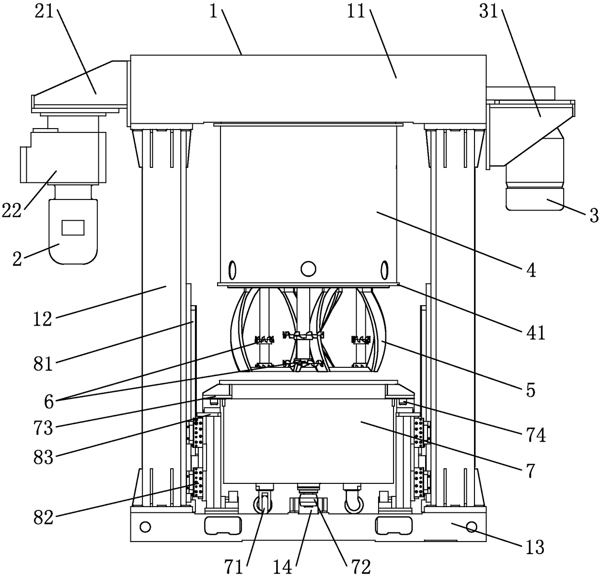
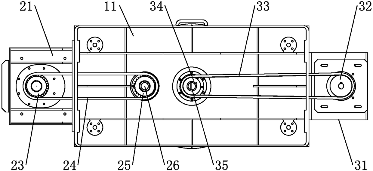
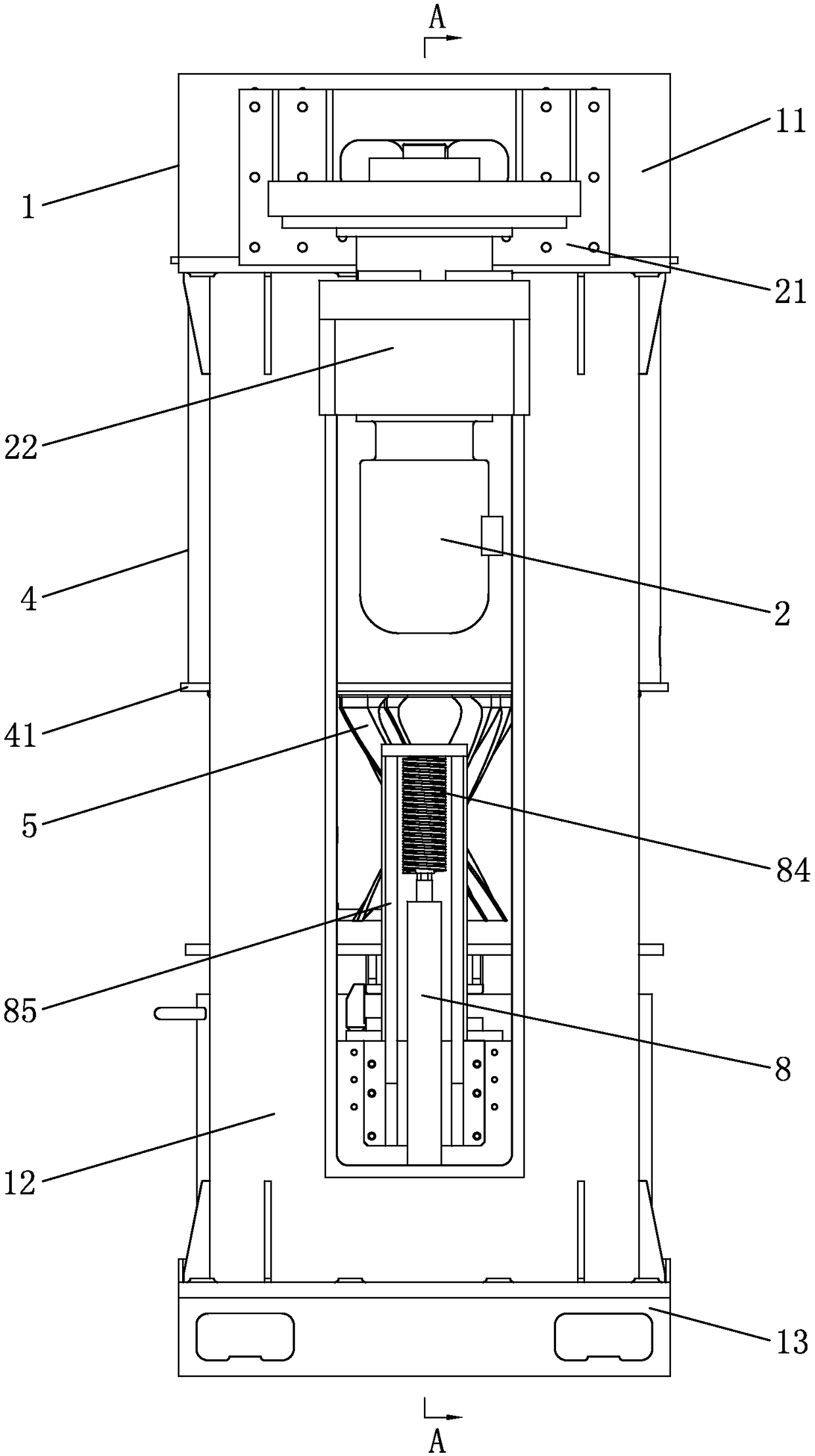
[0056] Embodiment one, see figure 1 - 8 and Figure 11 - As shown in 14, an industrial mixing and mixing equipment includes a gantry 1, the gantry 1 includes a base 13, a column 12 and a beam 11, the left and right sides of the top of the base 13 are provided with the column 12, and the two ends of the beam 11 are connected to the The top of the column 12 and the beam 11 are provided with a stirring mechanism, a dispersing mechanism, a fixed sleeve 4 and a protective cover 9 . Each part of the gantry 1 is casted, and the base 13 is provided with a lifting mechanism for the bucket 7. The lifting mechanism for the bucket 7 includes a bracket 83 for lifting movement, and a horizontal limit is provided between the bracket 83 and the bucket 7. structure. The hoisting mechanism of the bucket 7 also includes a servo electric cylinder 8, a vertical guide rail 81 and a slide block 82. The corresponding servo electric cylinder 8 is provided with a limit frame 85 on the gantry 1, and t...

Embodiment 2

[0070] Embodiment two, the difference with embodiment one is: see Figure 17 and Figure 18As shown, four stirring paddles 5 are provided, and four dispersion shafts 61 are provided. L1 is the outer peripheral rotation path of the four stirring paddles 5 when they rotate, and L2 is the inner wall of the material barrel 7 (the center of the inner cavity of the material barrel 7 can theoretically be It is understood as the rotation center of the protective cover 9, the two centers overlap or basically overlap), and the four small circles such as L3, L4, etc. are the outer peripheral rotation paths of the four dispersion shafts 61 corresponding to the dispersion disc 6 when they rotate; among them, the four The center point O' of the virtual plane formed by the sequential connection of O1, O2, O3 and O4 is respectively the center point of the rotation path of the stirring paddle 5, which deviates from the center point O of the inner cavity of the barrel 7.

Embodiment 3

[0071] Embodiment three, the difference with embodiment one is: see Figure 19 As shown, two stirring paddles 5 are provided, and two dispersion shafts 61 are provided. L1 is the outer peripheral rotation path of the two stirring paddles 5 during autorotation work, and L2 is the inner wall of the material barrel 7 (the center of the inner cavity of the material barrel 7 can theoretically be It is understood as the rotation center of the protective cover 9, the two centers overlap or basically overlap), L3 and L4 are the outer peripheral rotation paths corresponding to the dispersion disc 6 when the two dispersion shafts 61 rotate; wherein, the two stirring paddles 5 rotation rotation paths The centers of circles are the center point O' of the line connecting O1 and O2, which deviates from the center point O of the inner cavity of the barrel 7.


PUM


Abstract

The invention relates to industrial stirring equipment mainly used for mixing lithium-battery materials. The industrial stirring equipment comprises a rack, a stirring mechanism, a dispersing mechanism, a supporting component, a stirring driving device and a dispersion driving device, wherein the supporting component is rotatably matched with the rack; the stirring mechanism and the dispersing mechanism are respectively and rotatably arranged on the supporting component; the supporting component is provided with synchronous gears; the rack is provided with fixed gears; the synchronous gears are meshed with the fixed gears and rotate around the fixed gears. The industrial stirring equipment has the beneficial effects that stirring paddles of the stirring mechanism and dispersing shafts of the dispersing mechanism can realize autorotation and revolution simultaneously and can pass more areas, so that the mixing effect is improved; in addition, the stirring paddles and the dispersing shafts are respectively and independently driven by a stirring motor and a dispersing motor, so that the load of the motors is reduced and the working is more reliable.

Description

technical field [0001] The invention relates to a stirring device, in particular to an industrial stirring device mainly used for mixing lithium battery materials. Background technique [0002] With the progress and development of society, battery-driven products are becoming more and more popular. There are small electronic products, large vehicles (electric vehicles), etc. The driving batteries used in these products are basically lithium batteries, and lithium batteries The production of slurry involves stirring and mixing of various materials. However, the current mixing and mixing equipment generally has insufficient stirring and unevenness, resulting in large differences in the produced lithium battery slurry. For the final production of these lithium battery slurry The quality of lithium batteries varies greatly, which makes it difficult for large-scale high-power electrical equipment to use these lithium batteries, and also restricts the development of large-scale hi...

Claims


Application Information

Patent Timeline
Patent Type & Authority Applications(China)
IPC IPC(8): B01F7/30B01F7/26B01F15/00B01F27/93
CPCB01F27/2322B01F27/82B01F27/90B01F27/092B01F35/717B01F35/212Y02E60/10
Inventor 罗伟彬
Owner FOSHAN HONGRUIDE NEW ENERGY PRECISION EQUIP CO LTD
Why Eureka
Try Eureka