
Sizing frame after pipeline forming

A pipeline and water inlet pipe technology, applied in the field of setting frame, can solve the problems of long time required, inconvenient transportation and construction, insufficient strength, etc., and achieve the effects of convenient storage work, shortened setting time and simple structure

Inactive Publication Date: 2018-05-29
CHONGQING GUANGDA MACHINERY FACTORY CO LTD
View PDF1 Cites 0 Cited by
  • Summary
  • Abstract
  • Description
  • Claims
  • Application Information

AI Technical Summary

Problems solved by technology

[0002] The existing corrosive liquid transportation pipeline is easily corroded during use, has a limited service life, and needs to be replaced frequently. At the same time, it is prone to deformation under the action of external force, has insufficient strength, and poor impact resistance. A lot of noise. The applicant applied for a patent on the same day on December 16, 2015. The invention application number is 201521052340.5, and the name is a pressure-resistant protective layer. This design solves the above problems, but during production, the pipe wall is very thick , is also very heavy, which brings great inconvenience to transportation and construction
[0003] For this reason, the application also designs a set of metal pipes with corrugated structure, but when forming, it takes a long time to naturally cool and shape in the afternoon in the traditional way. For example, a 12-meter long pipe has a diameter of 100mm, about It takes about 10 hours. Such a cooling rate is not conducive to the storage of pipeline processing, and its setting space occupies too much space, which is about 0.5 times more than before.

Method used


Image

  • Sizing frame after pipeline forming

Examples


Embodiment 1

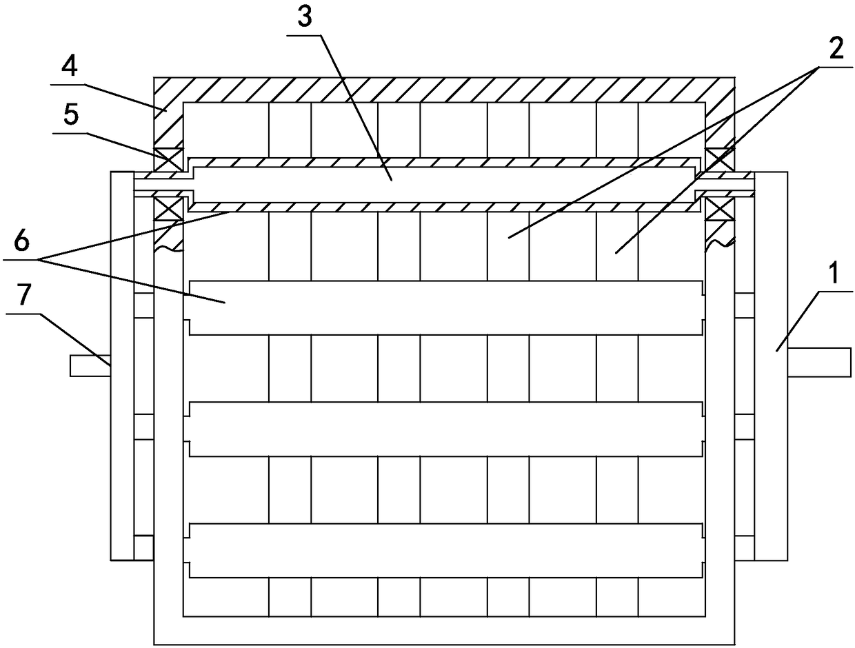
[0017] Such as figure 1 As shown, the calibrating frame after the pipeline is formed includes a frame support 4, on which a plurality of heat exchange rollers 6 that are freely rotating and arranged in parallel at equal intervals front and back are arranged, and the two ends of the heat exchange rollers 6 pass through the bearings 5 Installed on the frame support 4, each heat exchange roller 6 is provided with an exchange chamber 3, and on the right side of the frame support 4 is provided with a water inlet pipe 1, and the water inlet pipe 1 is connected to the right end of each heat exchange roller 6 and communicated with the exchange chamber 3 A water outlet pipe 7 is arranged on the left side of the frame bracket 4, and the water outlet pipe 7 is connected to the left end of each heat exchange roller 6 and communicated with the exchange chamber 3.

[0018] In this embodiment, the distance between the adjacent heat exchange rollers 6 is 10 cm; under the heat exchange rollers...

Embodiment 2

[0021] Based on the first embodiment, the distance between the adjacent heat exchange rollers 6 is 20 cm; the distance between the adjacent reinforcing rods 2 is 40 cm.

[0022] Others are the same as embodiment one.

Embodiment 3

[0024] Based on the first embodiment, the distance between the adjacent heat exchange rollers 6 is 30 cm; the distance between the adjacent reinforcing rods 2 is 50 cm.

[0025] Others are the same as embodiment one.


PUM


Abstract

The invention relates to a sizing frame after pipeline forming, and belongs to the technical field of brackets. The sizing frame comprises a frame bracket. The bracket is provided with a plurality ofheat exchanging rollers which rotate freely and are arranged in parallel front and back at equal intervals. The two ends of each heat exchanging roller are mounted on the frame bracket through bearings. Each heat exchanging roller is internally provided with an exchanging cavity. The right side of the frame bracket is provided with a water inlet pipe. The water inlet pipe is connected with the right end of each heat exchanging roller and communicates with the exchanging cavities. The left side of the frame bracket is provided with a water outlet pipe. The water outlet pipe is connected with the left end of each heat exchanging roller and communicates with the exchanging cavities. According to the sizing frame after pipeline forming, the structure is simple, the sizing time is shortened to2-3 hours, the size of the occupied space during pipeline sizing is effectively controlled, and the storage work after pipeline machining is facilitated.

Description

technical field [0001] The invention relates to a calibrating frame after a pipeline is formed, and belongs to the technical field of brackets. Background technique [0002] The existing corrosive liquid transportation pipeline is easily corroded during use, has a limited service life, and needs to be replaced frequently. At the same time, it is prone to deformation under the action of external force, has insufficient strength, and poor impact resistance. A lot of noise. The applicant applied for a patent on the same day on December 16, 2015. The invention application number is 201521052340.5, and the name is a pressure-resistant protective layer. This design solves the above problems, but during production, the pipe wall is very thick , is also very heavy, which brings great inconvenience to transportation and construction. [0003] For this reason, the application also designs a set of metal pipes with corrugated structure, but when forming, it takes a long time to natura...

Claims


Application Information

Patent Timeline
IPC IPC(8): B29C47/88B25H3/04
CPCB25H3/04B29C48/9115
Inventor 王彩红
Owner CHONGQING GUANGDA MACHINERY FACTORY CO LTD
Learn More