Site heat treatment device for air cylinder groove

A technology of heat treatment devices and grooves, applied in heat treatment furnaces, heat treatment equipment, furnaces, etc., can solve the problems of poor time control, difficult temperature control, and unsatisfactory heat treatment effects, etc., and achieve good heat treatment effects

Inactive Publication Date: 2018-05-29
四川中电福溪电力开发有限公司 +1
View PDF9 Cites 0 Cited by
  • Summary
  • Abstract
  • Description
  • Claims
  • Application Information

AI Technical Summary

Problems solved by technology

The online heat treatment of the cylinder groove adopts flame baking, but the temperature of this heat treatment method is difficult to control, and the time is not easy to control, so the heat treatment effect is not very ideal

Method used


Image

  • Site heat treatment device for air cylinder groove
  • Site heat treatment device for air cylinder groove
  • Site heat treatment device for air cylinder groove

Examples


Embodiment 1

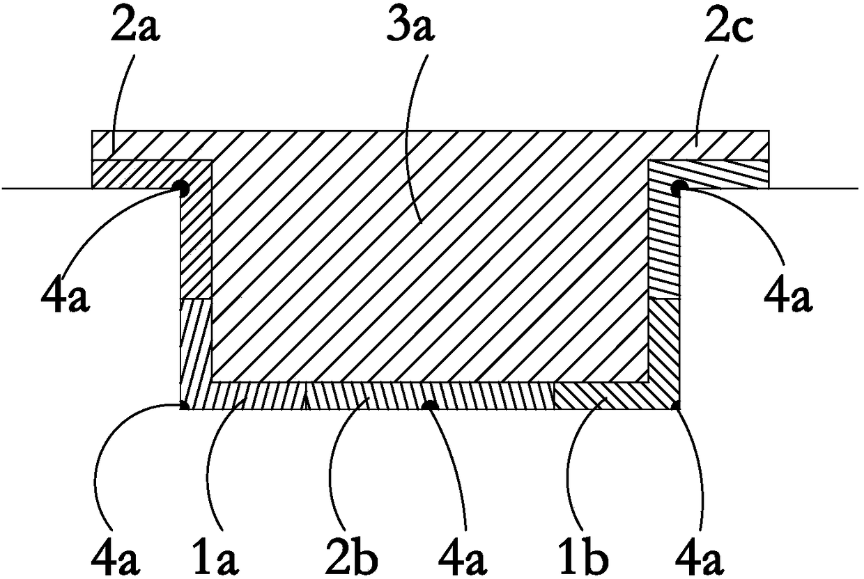
[0036] Such as figure 1 The heat treatment device shown is for heat treatment of the crack repair at the two corners of the cylinder groove bottom, the device body includes: the first main heating zone 1a, the second main heating zone 1b, the first auxiliary heating zone 2a, the second auxiliary The hot zone 2b, the third auxiliary heating zone 2c and the heat preservation zone 3a, the first auxiliary heating zone 2a, the first main heating zone 1a, the second auxiliary heating zone 2b, the second main heating zone 1b, and the third auxiliary heating zone 2c in sequence Connect and cover all the inner walls of the cylinder groove, and the first auxiliary heating zone 2a, the first main heating zone 1a, the second main heating zone 1b, and the third auxiliary heating zone 2c respectively cover the corner of a cylinder groove, and the second auxiliary heating zone The hot area 2b covers most of the bottom surface of the cylinder groove to provide auxiliary heat between the first...

Embodiment 2

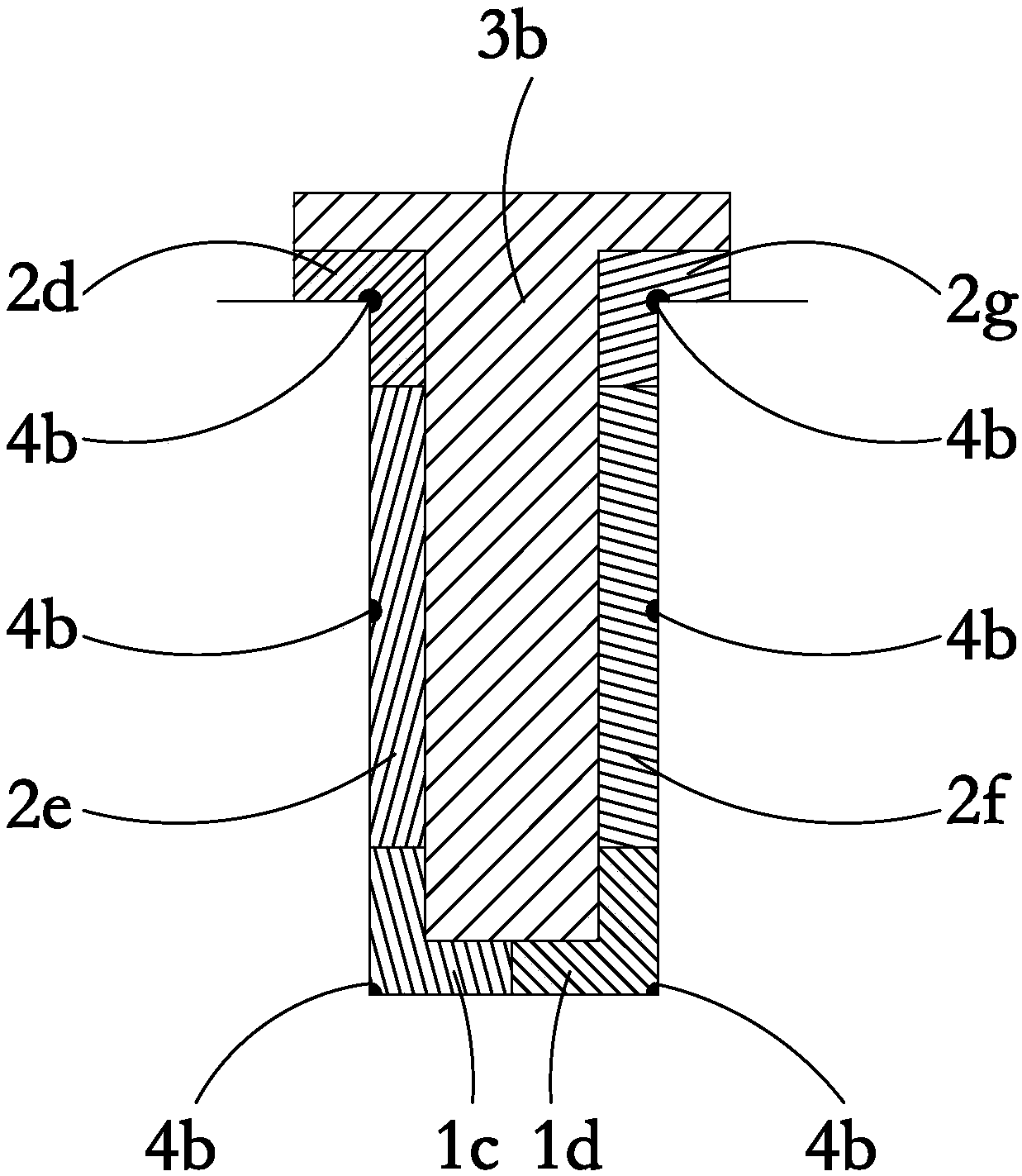
[0041] Such as figure 2 The heat treatment device shown is for heat treatment for crack repair at the two corners of the bottom of the cylinder groove. The device includes a first main heating zone 1c, a second main heating zone 1d, a first auxiliary heating zone 2d, and a second auxiliary heating zone 2e, the third auxiliary heating zone 2f, the fourth auxiliary heating zone 2g and the heat preservation zone 3b, the first auxiliary heating zone 2d, the second auxiliary heating zone 2e, the first main heating zone 1c, the second main heating zone 1d, the third The auxiliary heating area 2f and the fourth auxiliary heating area 2g are sequentially connected and cover the entire inner wall of the cylinder groove, and the first auxiliary heating area 2d, the first main heating area 1c, the second main heating area 1d, and the third auxiliary heating area 2e Covering the corners of one cylinder groove respectively, the heat preservation zone 3b covers the first auxiliary heating ...

Embodiment 3

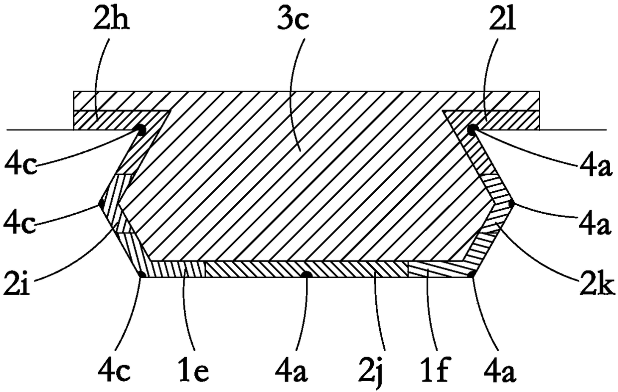
[0044] Such as image 3The heat treatment device shown is for heat treatment for crack repair at the two corners of the bottom of the cylinder groove. The device includes a first main heating zone 1e, a second main heating zone 1f, a first auxiliary heating zone 2h, and a second auxiliary heating zone 2i, the third auxiliary heating zone 2j, the fourth auxiliary heating zone 2k, the fifth auxiliary heating zone 2l and the heat preservation zone 3c, the first auxiliary heating zone 2h, the second auxiliary heating zone 2i, the first main heating zone 1e, the third The auxiliary heating area 2j, the second main heating area 1f, the fourth auxiliary heating area 2k, and the fifth auxiliary heating area 2l are sequentially connected and cover the entire inner wall of the cylinder groove, and the first auxiliary heating area 2h, the second auxiliary heating area 2i , the first main heating zone 1e, the second main heating zone 1f, the fourth auxiliary heating zone 2k, and the fifth...


PUM


Abstract

The invention relates to a site heat treatment device for an air cylinder groove, which comprises a device main body and a control system; the device main body is provided with a main heating zone andan assistant heating zone; the main heating zone covers a to-be-repaired position of the air cylinder groove, and the assistant heating zone is located in at least one side of the main heating zone;heating components are arranged in the main heating zone and the assistant heating zone; the control system is connected with the heating component for controlling the work of the heating component and the heating temperature. Through the main heating zone, the to-be-repaired zone is heated; the main heating zone is performed with assistant heating and heat insulation through the assistant heatingzone, so as to realize heat treatment of every part of the groove; the heat treatment temperature and time are effectively controlled, thus no partial overheat is guaranteed; the main heating zone and the assistant heating zone can be set and switched according to the repair zone; the heat treatment effect is good.

Description

technical field [0001] The invention relates to a heat treatment device, in particular to an on-site heat treatment device for cylinder grooves. Background technique [0002] The corner area of ​​the cylinder groove is a stress concentration area, which is prone to cracks, thus affecting its normal use. In the prior art, when a crack occurs in the cylinder groove, it will be repaired, usually by welding, and then heat treated after welding. The online heat treatment of the cylinder groove adopts flame baking, but the temperature and time of this heat treatment method are difficult to control, so the heat treatment effect is not very ideal. Contents of the invention [0003] The object of the present invention is to provide a device for on-site heat treatment of cylinder grooves. [0004] In order to achieve the above object, the technical scheme adopted in the present invention is: [0005] A device for on-site heat treatment of cylinder grooves, comprising: [0006] D...

Claims


Application Information

Patent Timeline
Patent Type & Authority Applications(China)
IPC IPC(8): C21D9/00C21D1/34
CPCC21D9/0068C21D1/34
Inventor 杨太勇梁红兵马为民赵灿韩勇吕一仕赵建仓王淦刚
Owner 四川中电福溪电力开发有限公司
Why Eureka
Try Eureka