
Thermomechanical treatment equipment and process method thereof

A deformation heat treatment and process method technology, applied in heat treatment equipment, heat treatment furnaces, manufacturing tools, etc., can solve the problems affecting the fatigue life and tensile strength of coiled tubing, fractures or grooves, coarse grains, etc., and achieve process control visualization. , The effect of eliminating residual stress and improving hardness

Pending Publication Date: 2021-04-09
XINDA KECHUANG TANGSHAN PETROLEUM EQUIP CO LTD
View PDF0 Cites 0 Cited by
  • Summary
  • Abstract
  • Description
  • Claims
  • Application Information

AI Technical Summary

Problems solved by technology

[0002] There is a thermal induction zone during welding of the coiled tubing plate. The grains in the induction zone are coarse, the hardness is soft, and the strength of the weld is high. There is a large hardness contrast between the thermal induction zone and the weld. , when welded into coiled tubing, fractures or grooves are prone to occur at this position, which seriously affects the fatigue life and tensile strength of coiled tubing

Method used


Image

  • Thermomechanical treatment equipment and process method thereof
  • Thermomechanical treatment equipment and process method thereof

Examples


Embodiment 1

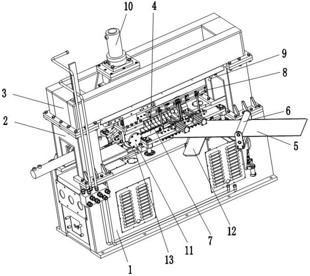
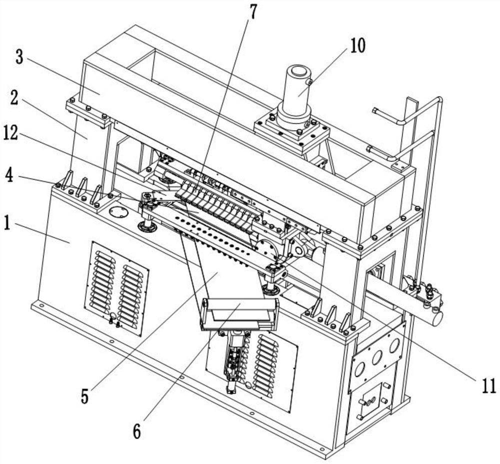
[0027] like figure 1 , figure 2 As shown, a deformation heat treatment equipment includes a body 1, a frame body 2 and a top seat 3, the top seat 3 is connected to the top of the body 1 through the frame body 2, and the upper surface of the body 1 is provided with a processing position 4. A steel belt 5 is placed at the processing position 4, and the steel belt 5 is guided into the processing position 4 by the steel belt guide wheel 6, and the two sides of the processing position 4 can be raised and lowered and symmetrically provided with a steel belt pressing device 7. The upper holding device 7 of the steel strip can press down and clamp the two ends of the steel strip 5, and one side of the processing position 4 is provided with a weld seam protection device that can be buckled on the steel strip 5 8 and the lower backing plate 12 that can move to the bottom of the steel belt 5, the lower heating intermediate frequency probe 13 is set under the processing position 4, and ...

Embodiment 2

[0041] A deformation heat treatment process method, comprising the following steps:

[0042] Step 1, aligning the welding seam of the steel strip 5 and the lower heating intermediate frequency probe 13 through the laser on the top seat 3;

[0043] Step 2, the steel strip upper holding device 7 presses and clamps the two ends of the steel strip 5 to prevent the steel strip 5 from moving;

[0044] Step 3, turn and buckle the weld seam protection device 8 onto the weld seam, and heat at a heating temperature of 700°C-800°C, and keep warm for 8s-15s;

[0045]Step 4, turn the weld protection device 8 away from the weld, lift the upper holding device 7 and the steel belt 5 on the steel belt, put it under the steel belt 5 and move it into the lower backing plate 12, then put down the steel belt 5, and the upper holding device on the steel belt 7 Fix the steel belt 5 downwards, the driving cylinder drives the rolling wheels of the rolling head 11 to move back and forth, and then the ...


PUM


Abstract

The invention discloses thermomechanical treatment equipment and a process method thereof. The thermomechanical treatment equipment comprises a machine body, a frame body and a top seat, the top seat is connected to the upper portion of the machine body through the frame body, a machining station is arranged on the upper surface of the machine body, a steel belt is placed at the machining station, and the steel belt is guided into the machining station through a steel belt guide wheel; steel belt upper pressing devices are symmetrically arranged at the two sides of the machining station in a liftable manner, the steel belt upper pressing devices can press and clamp the two ends of the steel belt, and a welding seam protection device capable of being buckled on the steel belt and a lower base plate capable of moving to the position below the steel belt are arranged at one side of the machining station; and a lower heating medium-frequency probe is arranged below the machining station, and a rolling machine head capable of moving and ascending and descending is arranged above the machining station. By means of the thermomechanical treatment equipment, the hardness of a weld joint and the hardness of a thermal induction area can be more similar, residual stress of the weld joint is eliminated, the hardness and structure are more similar to or slightly better than those of base metal, and therefore the fatigue life and the tensile strength of a coiled tubing are guaranteed.

Description

technical field [0001] The invention relates to the technical field of material heat treatment, in particular to a deformation heat treatment equipment and a process method thereof. Background technique [0002] There is a thermal induction zone during welding of the coiled tubing plate. The grains in the induction zone are coarse, the hardness is soft, and the strength of the weld is high. There is a large hardness contrast between the thermal induction zone and the weld. , when welded into coiled tubing, fractures or grooves are prone to occur at this position, which seriously affects the fatigue life and tensile strength of coiled tubing. Contents of the invention [0003] The purpose of the present invention is to provide a deformation heat treatment equipment and its process method, which can solve the above-mentioned problems existing in the prior art. [0004] In order to solve the above-mentioned technical problems, the present invention adopts the following techn...

Claims


Application Information

Patent Timeline
Patent Type & Authority Applications(China)
IPC IPC(8): C21D9/50C21D8/02
CPCC21D9/50C21D8/0247C21D8/0221
Inventor 段建良董健刘佳俊张雅丽孙启发刘月明
Owner XINDA KECHUANG TANGSHAN PETROLEUM EQUIP CO LTD
Learn More