Combined dynamic and static grouting foundation reinforcement method

A technology of foundation reinforcement and construction method, which is applied in basic structural engineering, construction, soil protection, etc., to solve the poor adaptability of soil conditions, improve the utilization rate, and expand the scope of reinforcement.

Active Publication Date: 2019-12-31
SHENZHEN YJY BUILDING TECH +1
View PDF9 Cites 0 Cited by
  • Summary
  • Abstract
  • Description
  • Claims
  • Application Information

AI Technical Summary

Problems solved by technology

[0003] Aiming at the above-mentioned shortcomings that the single grouting method in the prior art is difficult to meet the needs of various types of ground reinforcement, the present invention provides a combined dynamic and static grouting foundation reinforcement method. After the construction of the lead hole is completed, the drill bit and Put the grouting pipeline into the design required reinforcement depth; install the orifice pressure regulating and sealing device in time; start the high-pressure jet grouting operation after the installation is completed, first stop spraying in place, and wait for the grout to be blocked to form a certain pressure, then pass The pressure regulating device controls the pressure in the hole within the design requirements; when the drill bit is lifted for high-pressure rotary spraying, the static pressure grouting mode is automatically started, and the pressure in the hole is adjusted through the pressure regulating device to ensure high-pressure jet grouting and static pressure grouting The organic combination of the slurry effect; the soil is fully mixed and solidified to form an effective reinforced soil

Method used


Image

  • Combined dynamic and static grouting foundation reinforcement method
  • Combined dynamic and static grouting foundation reinforcement method
  • Combined dynamic and static grouting foundation reinforcement method

Examples


Embodiment Construction

[0030] This embodiment is a preferred implementation mode of the present invention, and other principles and basic structures that are the same or similar to this embodiment are within the protection scope of the present invention.

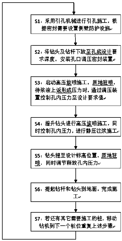
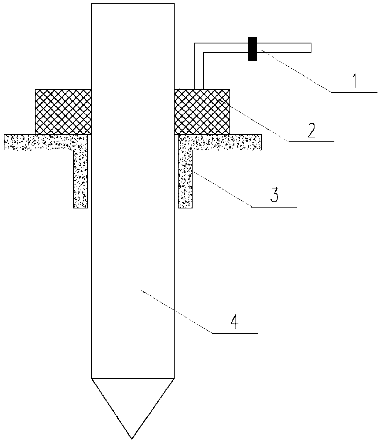
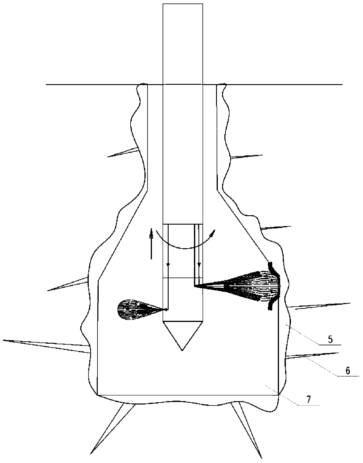
[0031] Please see attached figure 1 , attached figure 2 And attached image 3 , the present invention is mainly a kind of joint dynamic and static grouting foundation reinforcement engineering method, and this method mainly comprises the following steps:

[0032] Step S1: Use the hole-leading machine to carry out the hole construction, and install the side wall protection device 3 according to the sealing requirements. In this embodiment, the hole side wall protection device 3 can use various side walls such as steel casing, cement or concrete protection wall, etc. Protective measures can ensure the sealing effect. In this embodiment, according to the different choices of side wall protection methods, the installation of side wall protection de...


PUM


Abstract

The invention discloses a dynamic and static combined grouting foundation reinforcement method. The method comprises the following steps of S1, hole-guiding construction is carried out by adopting a hole-guiding machine, and a side wall protection device is arranged; S2, injection reinforcement slurry treatment is carried out by adopting a high-pressure jet drilling tool, an orifice sealing deviceis installed at an orifice before injection, and an orifice pressure regulating device is connected to the orifice sealing device; S3, a high-pressure rotary spraying construction is started, and parking and spraying construction is carried out in situ, and the pressure in the orifice is controlled through the orifice pressure regulating device to reach a design requirement value; S4, the high-pressure jet drilling tool is lifted to carry out high-pressure rotary spraying construction, the rotating speed of the high-pressure jet drilling tool is 8 -25 r / min, the lifting speed is 6-25 cm / min,and meanwhile, the pressure in the control hole is adjusted; S5, the drill bit is lifted to a designed elevation position, in-situ parking is carried out and the pressure in the release hole is adjusted; S6, the drill rod and the drill bit are lifted to the ground, and construction of the pile body is completed; and S7, the drilling machine is moved to the next pile position, the step S1 to the step S6 are repeated, and finally the work is completed.

Description

technical field [0001] The invention discloses a foundation reinforcement method, in particular a dynamic and static combined grouting foundation reinforcement method, and relates to the fields of foundation reinforcement treatment and water stop treatment of geotechnical engineering under various geological conditions. Background technique [0002] At present, conventional grouting methods are divided into static pressure grouting and high-pressure jet grouting. Among them, the static pressure grouting method is suitable for geological conditions such as medium-coarse sand, gravel, and broken rock, but is not suitable for fine-grained soil such as silt and clay. Moreover, the controllability of the grout is poor, and the phenomenon of grouting and running often occurs. It is difficult to achieve global reinforcement for filling pebbles that are easy to concentrate; the high-pressure jet grouting method is suitable for sandy soil, cohesive soil, silty soil and other strata, ...

Claims


Application Information

Patent Timeline
Patent Type & Authority Patents(China)
IPC IPC(8): E02D3/12
CPCE02D3/12
Inventor 吴旭君闫贵海骆永生王召磊郑平高焰林谷霖
Owner SHENZHEN YJY BUILDING TECH
Why Eureka
Try Eureka