Wall automatic heat collection and heat dissipation system and method of using it to realize wall heat collection and heat dissipation

A heat removal system and wall technology, applied to walls, heat storage equipment, indirect heat exchangers, etc., can solve the problems of inability to effectively meet the heat preservation and heat collection of building envelopes in winter, high installation costs, and difficult implementation. Achieve the effects of improving the scope of application and adjustable performance, reducing energy consumption, and improving adjustability

Active Publication Date: 2019-10-15
武汉捷高技术有限公司
View PDF1 Cites 0 Cited by
  • Summary
  • Abstract
  • Description
  • Claims
  • Application Information

AI Technical Summary

Problems solved by technology

Although the above-mentioned device and method can meet the needs of building heat insulation in summer to a certain extent, and can achieve the purpose of reducing energy consumption to a certain extent; however, the wall in the above-mentioned device and method adopts the form of nesting inner and outer tubes, and must Phase change materials, circulating working fluid and other materials cooperate with each other, the structure is more complicated, the realization is more difficult, the maintenance is more difficult, and the installation cost is also higher. Moreover, the above-mentioned devices and methods can only achieve the heat dissipation of the wall in summer to a certain extent, and cannot Effectively meet the needs of thermal insulation and heat collection of building envelopes in winter, but there are major limitations, and its applicability is small

Method used


Image

  • Wall automatic heat collection and heat dissipation system and method of using it to realize wall heat collection and heat dissipation
  • Wall automatic heat collection and heat dissipation system and method of using it to realize wall heat collection and heat dissipation
  • Wall automatic heat collection and heat dissipation system and method of using it to realize wall heat collection and heat dissipation

Examples


Embodiment Construction

[0033] In order to make the object, technical solution and advantages of the present invention clearer, the present invention will be further described in detail below in conjunction with the accompanying drawings and embodiments. It should be understood that the specific embodiments described here are only used to explain the present invention, not to limit the present invention.

[0034] In addition, the technical features involved in the various embodiments of the present invention described below can be combined with each other as long as they do not constitute a conflict with each other.

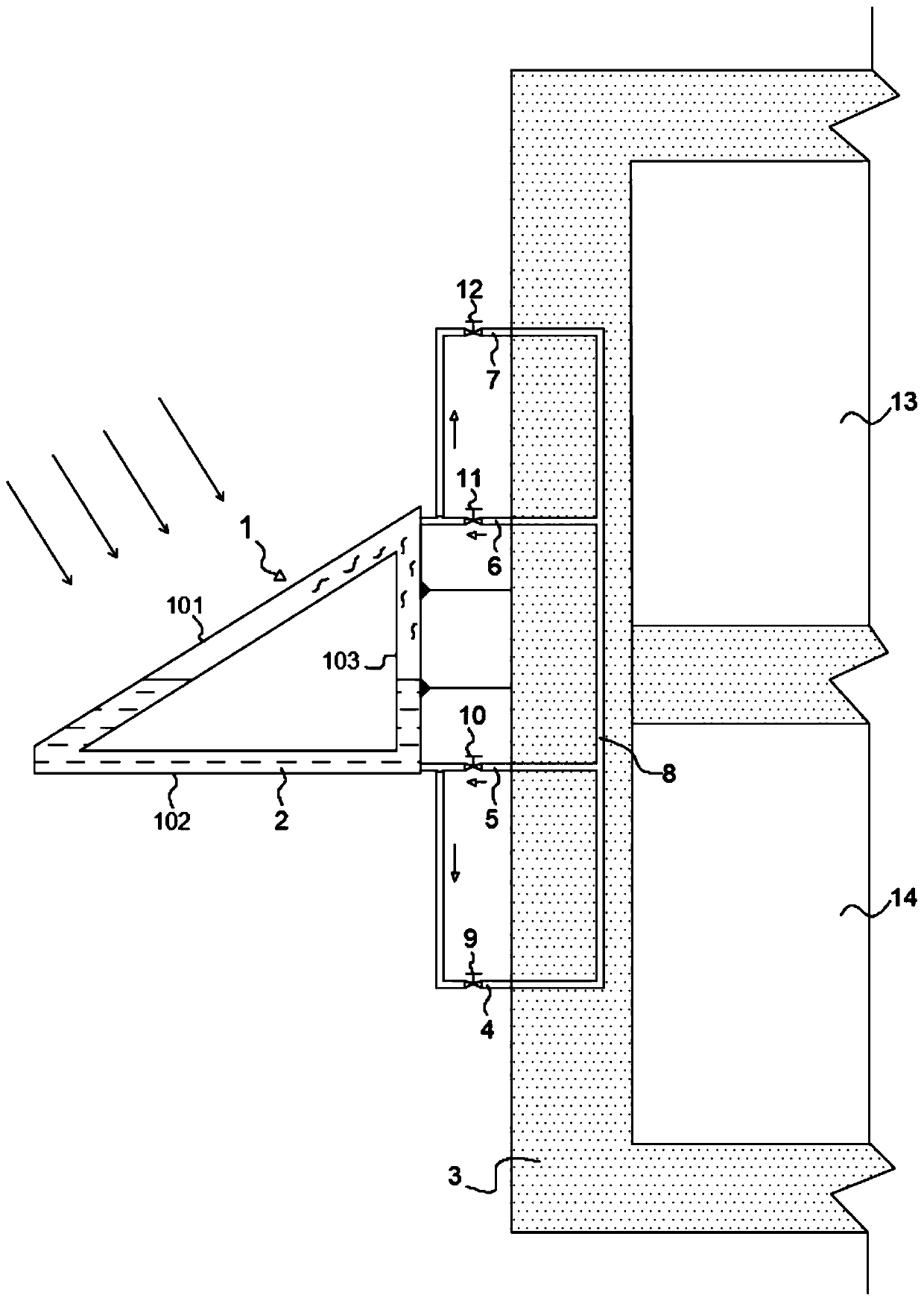
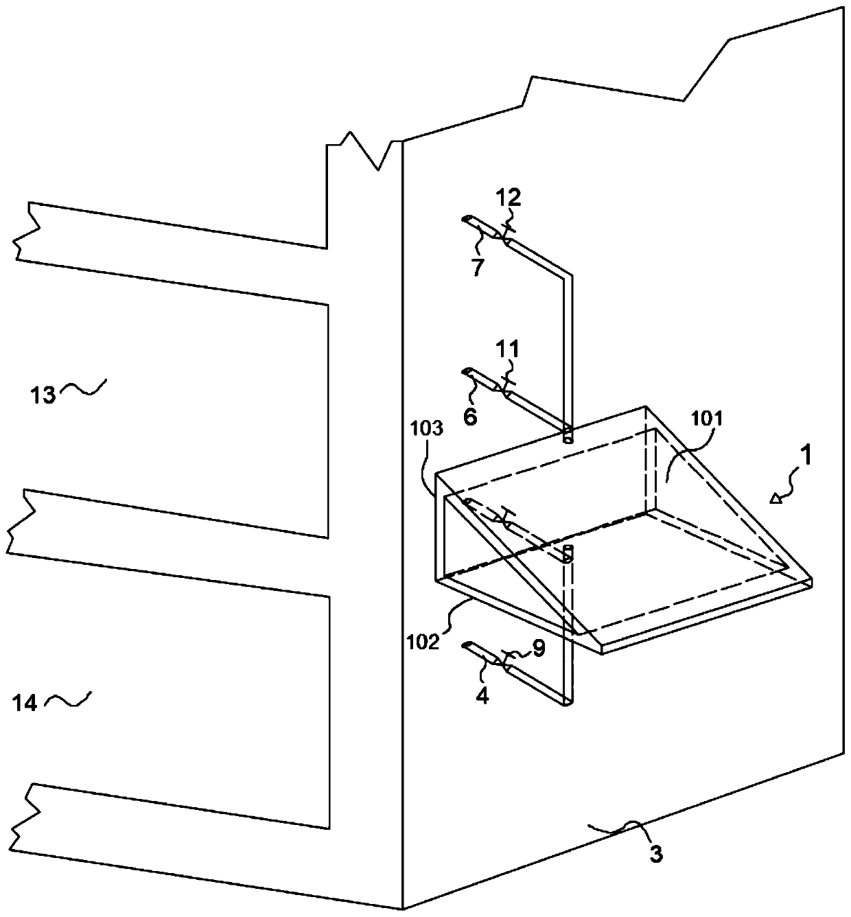
[0035] The wall automatic heat collection and heat dissipation system in a preferred embodiment is as figure 1 and figure 2 shown in , where, figure 1 It is a cross-sectional view of the system structure of the wall automatic heat collection and discharge system in the embodiment of the present invention; figure 2 It is a three-dimensional view of the system structure of the wall a...


PUM


Abstract

The invention discloses an automatic heat collection and dissipation system for a wall body and a method for utilizing the system to achieve heat collection and dissipation of the wall body, and belongs to the field of building energy conservation and renewable energy resource utilization. Radiation plate assemblies are arranged on the outer wall of the wall body, embedded pipes are vertically arranged in the wall body, a sealed cavity structure adjustable in vacuum degree is arranged in each radiation plate assembly, a cycle working fluid is contained in each sealed cavity structure, and a cycle working fluid circulating pipeline is arranged to make the radiation plate assemblies communicated with the embedded pipes, so that a sealed cycle working fluid circulating loop is formed, and heat collection or heat dissipation of the wall body is completed by means of state changes and cyclic flowing of the cycle working fluid. The system is simple in structure and easy to array and maintain, and the method for utilizing the system to achieve heat collection and dissipation of the wall body is simple and easy to operate and control; moreover, the adjustable range of the system is wide, the system can be effectively applied to heat collection and heat dissipation of the wall body in different environments during different seasons and is excellent in adaptability, great in economic efficiency and capable of greatly reducing energy consumption and waste of resources.

Description

technical field [0001] The invention belongs to the field of building energy saving and renewable energy utilization, and in particular relates to an automatic heat collection and discharge system for walls and a method for realizing heat collection and discharge for walls by utilizing the same. Background technique [0002] In recent years, with the continuous improvement of people's living standards, people's requirements for the indoor environment of buildings are getting higher and higher, and the energy consumption of heating and air conditioning accounts for an increasing proportion of the total energy consumption of buildings; To meet the needs of environmental protection, it is very important to reduce building energy consumption. Therefore, more and more new building energy-saving technologies have attracted widespread attention. In the energy consumption of building heating and air conditioning, the cooling and heating load formed by the heat transfer through the b...

Claims


Application Information

Patent Timeline
Patent Type & Authority Patents(China)
IPC IPC(8): E04B1/74E04B2/00F28D20/02
CPCE04B1/74E04B2/00F28D20/021F28D21/00F28D2021/0035Y02E60/14Y02E70/30
Inventor 徐新华高佳佳阮长龙严天
Owner 武汉捷高技术有限公司
Why Eureka
Try Eureka