Vehicle, vehicle cooling system and electronic water pump control method of inter-cooling device of vehicle cooling system

An electronic water pump and control method technology, applied in pump control, charging system, liquid variable capacity machinery, etc., can solve problems such as increasing air intake resistance, blocking air intake channels, and freezing of intercooling devices

Active Publication Date: 2018-05-29
NINGBO GEELY ROYAL ENGINE COMPONENTS
View PDF4 Cites 7 Cited by
  • Summary
  • Abstract
  • Description
  • Claims
  • Application Information

AI Technical Summary

Problems solved by technology

[0006] Problem 1: Because the full-load crankcase ventilation system is ventilated from the front of the supercharger, the oil vapor carried by the crankcase ventilation system will adhere to the water-cooled intercooler to form oil droplets; and when the engine is added to EGR, the condensation generated Water, condensed water and oil droplets form an emulsion, which blocks part of the air intake passage of the water-cooled intercooler, increases air intake resistance, and affects engine performance
[0007] Problem 2: When the vehicle is in a cold area, after the vehicle stops running, the condensed water generated by the intake system will easily cause the intercooler to freeze; when it is restarted, the intake resistance will increase sharply, which will seriously affect the engine performance

Method used


Image

  • Vehicle, vehicle cooling system and electronic water pump control method of inter-cooling device of vehicle cooling system
  • Vehicle, vehicle cooling system and electronic water pump control method of inter-cooling device of vehicle cooling system

Examples


Embodiment Construction

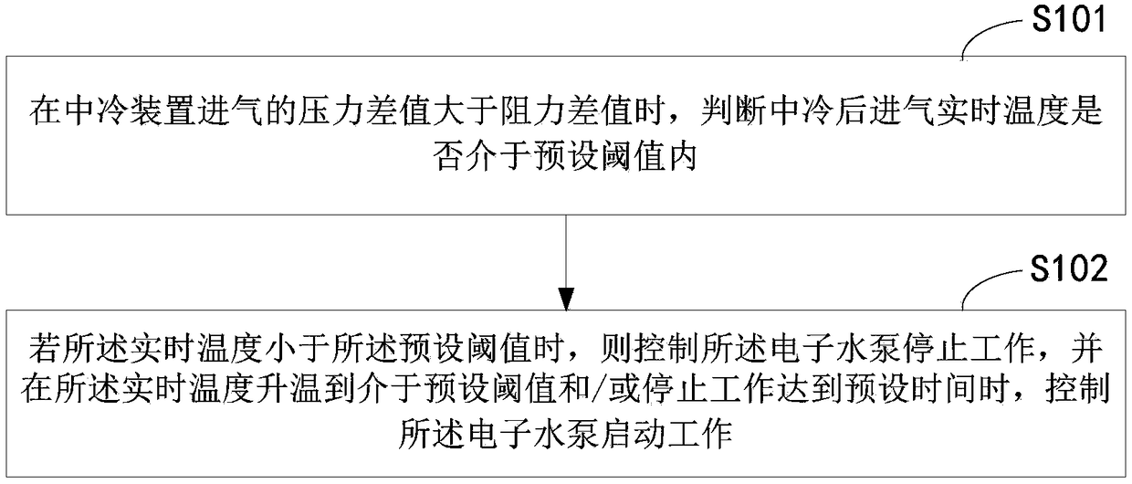
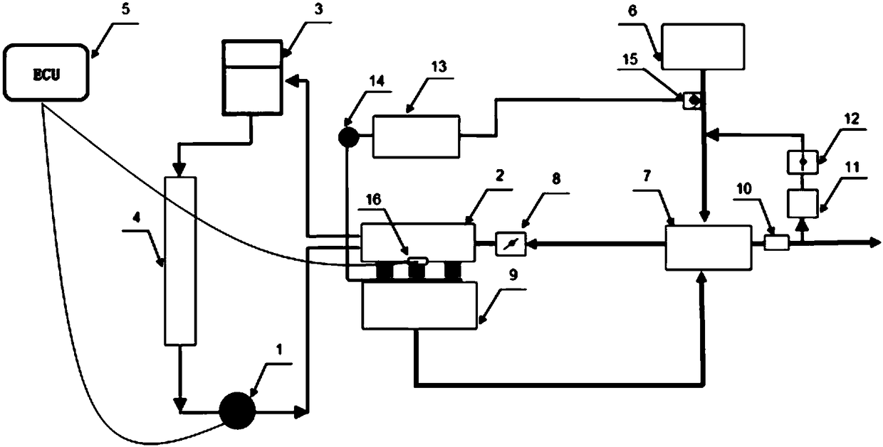
[0031] In order to further explain the technical means and effects of the present invention to achieve the intended purpose of the invention, the specific implementation methods, methods, and steps of the Hall sensor device and terminal proposed according to the present invention will be described below in conjunction with the accompanying drawings and preferred embodiments. , structure, feature and effect thereof are described in detail as follows.

[0032] The foregoing and other technical contents, features and effects of the present invention will be clearly presented in the following detailed description of preferred embodiments with reference to the drawings. Through the description of the specific implementation mode, the technical means and effects adopted by the present invention to achieve the predetermined purpose can be understood more deeply and specifically, but the attached drawings are only for reference and description, and are not used to explain the present i...


PUM


Abstract

The invention relates to a vehicle, a vehicle cooling system and an electronic water pump control method of an inter-cooling device of the vehicle cooling system. The method comprises the steps that whether the real-time air inlet temperature after inter-cooling is in the preset threshold or not is judged, and if the real-time temperature is less than the preset threshold, an electronic water pumpis controlled to stop working; and when the real-time temperature rises to the preset threshold and / or when the water pump stops working for the preset-time, the electronic water pump is controlled to start working. By controlling the running state of the electronic water pump of the inter-cooling device, the electronic water pump is controlled to stop working, the air inlet temperature is increased after the inter-cooling until the air inlet temperature after the inter-cooling is higher than a set value, and then the electronic water pump is started, so that the mixture of engine oil and condensate water in the inter-cooling device are volatilized, and the problem of the drop and increase of the front and rear air inlet pressure of the inter-cooling device is alleviated; and by controlling the electronic water pump to stop working in a cold environment, the air inlet cooling is avoided, the rise of the air inlet temperature is accelerated, and when the air inlet temperature after theinter-cooling is higher than a set value, the electronic pump is started, so that the problems of freezing and the like are solved.

Description

technical field [0001] The present application relates to the technical field of cooling systems, in particular to an electronic water pump control method of an intercooler, a vehicle and its cooling system. Background technique [0002] With the development of society and the improvement of people's living standards, automobiles have increasingly become an important means of transportation for people to travel. Automobiles include engines, and the temperature of the engine will increase during the running of the automobile. Therefore, it is necessary to dissipate heat from the engine to To ensure the normal operation of the engine, the traditional ways to cool the intake air temperature of the engine mainly include air-cooled and water-cooled. [0003] EGR (English full name: Exhaust Gas Recirculation, Chinese translation: Exhaust Gas Recirculation) technology plays an important role in engine fuel saving and emission reduction. With the increasingly stringent fuel consump...

Claims


Application Information

Patent Timeline
Patent Type & Authority Applications(China)
IPC IPC(8): F02B29/04F02M26/22F04B49/06
CPCF02B29/04F02M26/22F04B49/06Y02T10/12
Inventor 陈东亚韦虹李军王瑞平
Owner NINGBO GEELY ROYAL ENGINE COMPONENTS
Why Eureka
Try Eureka