
LED lamp panel assembly, LED photoelectric module and LED ceiling lamp

A technology of LED ceiling lamps and LED light boards, applied in the field of lighting, can solve problems such as increased reliability risks and complex processes, and achieve the effects of improving cost performance, saving production costs, and simple and direct electrical connections

Inactive Publication Date: 2018-05-29
ETI SOLID STATE LIGHTING ZHUHAI LTD
View PDF4 Cites 1 Cited by
  • Summary
  • Abstract
  • Description
  • Claims
  • Application Information

AI Technical Summary

Problems solved by technology

However, due to its multiple distributed PCB light boards, it is necessary to realize the electrical connection of multiple lamps through structural methods such as shrapnel. In addition to the complicated process, the structure like shrapnel easily increases the risk of reliability.

Method used


Image

  • LED lamp panel assembly, LED photoelectric module and LED ceiling lamp
  • LED lamp panel assembly, LED photoelectric module and LED ceiling lamp
  • LED lamp panel assembly, LED photoelectric module and LED ceiling lamp

Examples


Embodiment 1

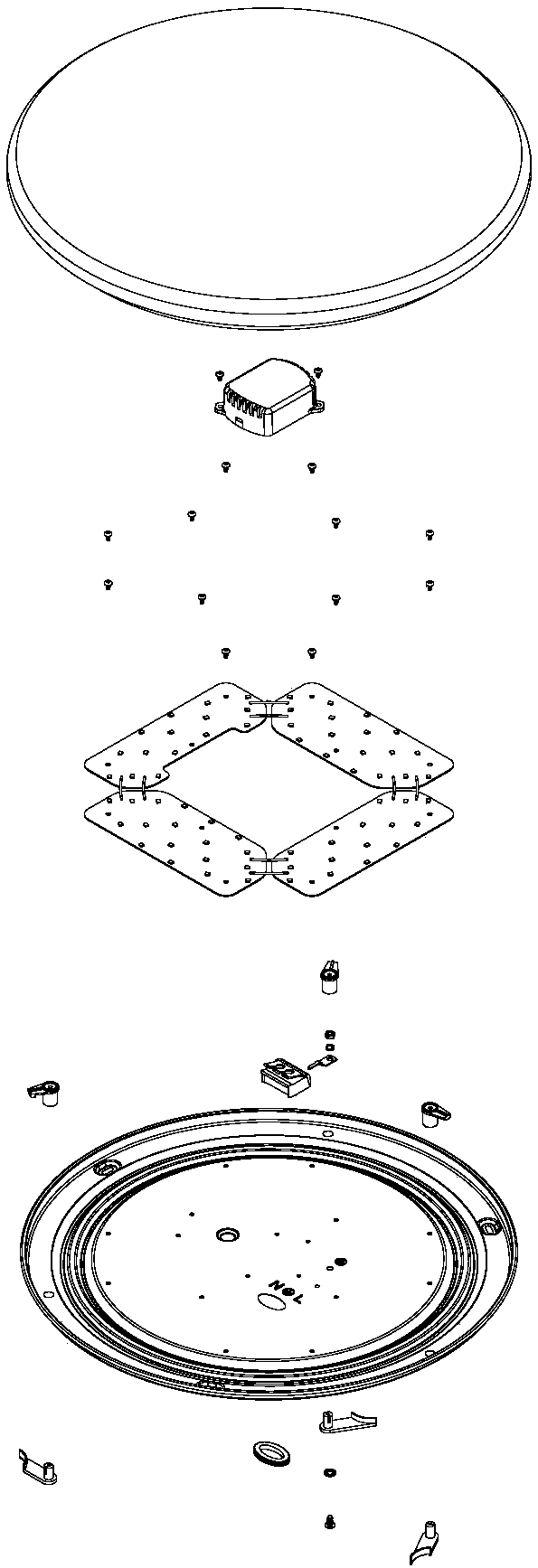
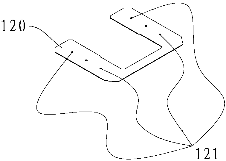
[0050] Such as image 3 and Figure 4 As shown, the LED lamp board assembly of the present invention includes a PCB lamp board 120 and several LED lamp beads 130 arranged on the PCB lamp board 120. The PCB lamp board 120 is a U-shaped lamp board, and the PCB lamp board 120 has two equal-width For the longitudinal side and the horizontal side connecting the two longitudinal sides, the width between the two longitudinal sides of the PCB light board 120 is equal to twice the width of each longitudinal side, such as Figure 5 As shown, H is the width between the two longitudinal sides of the PCB light board 120, that is, the width of the vacant slot in the middle of the two longitudinal sides, A is the width of each longitudinal side of the PCB light board 120, and the width between the two longitudinal sides of the PCB light board 120 is The width is equal to twice the width of each longitudinal side, ie H=2A.

[0051] Such a U-shaped structure can ensure that the PCB lamp pane...

Embodiment 2

[0064] refer to Figure 14-16 , embodiment 2 is for higher power ceiling lamps, when a larger or longer power driver is required, in order to obtain better light distribution on the outer lampshade, and there is not enough space on the lens to place the power driver, the power driver The scheme fixed on the chassis 210. Such as Figure 10-13 As shown, the volume of the power driver in this embodiment is relatively large, and the longitudinal sides of the LED light board 220 are relatively long. The power driver is fixed on the chassis 210 between the two longitudinal sides of the LED light board. The groove reserves the position of the mounting hole 211 on the chassis 210 .

[0065] The assembly process is as follows: the LED lamp bead 230 and the connection terminal 240 are fixed to the PCB light board 220 by patching to form an LED light board assembly. Then, the assembly of the lens assembly 250 composed of the lens base 251 and the lens 252 and the LED lamp board assemb...


PUM


Abstract

The invention discloses an LED lamp panel assembly, an LED photoelectric module and an LED ceiling lamp, and relates to the technical field of illumination. The invention provides the LED lamp panel assembly provided with a module function, the LED photoelectric module provided with the LED lamp panel assembly, and the LED ceiling lamp provided with the LED photoelectric module; and the LED lamp panel assembly, the LED photoelectric module and the LED ceiling lamp are low in cost, and simple and direct in electrical connection. The LED lamp panel assembly comprises a PCB lamp panel and multiple LED lamp beads arranged on the PCB lamp panel; the PCB lamp panel is a U-shaped lamp panel; the PCB lamp panel is provided with two longitudinal edges with same width and two transversal edges connected with the two longitudinal edges; and the width of the two longitudinal edges of the PCB lamp board is two times the width of each longitudinal edge.

Description

technical field [0001] The invention relates to the technical field of lighting, in particular to an LED lamp panel assembly, an LED photoelectric module and an LED ceiling lamp. Background technique [0002] LED is a new type of semiconductor solid-state light source. It is a granular light-emitting element. With many advantages such as environmental protection, energy saving, long life, and safety, LED light source has long been the lighting industry in the context of creating a conservation and environmental protection society. mainstream promotional products. For manufacturing companies, the competition in the development and manufacture of LED lighting products has shifted from the competition that focused on a single light flux and light efficiency in the early stage to the competition that focuses on product reliability or price competition under homogeneity. Or series product competition. [0003] The price of LED lighting products comes from the manufacturing cost...

Claims


Application Information

Patent Timeline
Patent Type & Authority Applications(China)
IPC IPC(8): F21S8/04F21V19/00F21V23/00F21V5/04F21Y115/10F21Y105/10
CPCF21S8/04F21V5/04F21V19/00F21V23/00F21V19/001F21V23/003
Inventor 王冬雷李廷宏苏涛
Owner ETI SOLID STATE LIGHTING ZHUHAI LTD
Learn More