Ground source heat pump mounting auxiliary device

An installation-assisted, ground-source heat pump technology, applied in heat pumps, lighting and heating equipment, refrigeration components, etc., can solve the problem that the drilling machine cannot perform drilling operations, affect the construction progress, reduce the drilling speed, etc., and achieve convenient field conditions. work, improve the burial speed, and ensure the effect of construction quality

Inactive Publication Date: 2018-05-29
山东一源能源科技开发有限公司
View PDF0 Cites 4 Cited by
  • Summary
  • Abstract
  • Description
  • Claims
  • Application Information

AI Technical Summary

Problems solved by technology

According to the current actual engineering, the main disadvantages of manual lowering are: slow speed, a large amount of manpower, a large workload, and a long construction period
The mechanical downpipe mainly uses the drilling machine to assist the downpipe, but when the drill pipe is used to assist the downpipe, the drilling machine cannot perform the drilling operation, which reduces the drilling speed and affects the construction progress, and it is easy to cause replacement during the downpipe process. heater damage

Method used


Image

  • Ground source heat pump mounting auxiliary device
  • Ground source heat pump mounting auxiliary device
  • Ground source heat pump mounting auxiliary device

Examples


Embodiment 1

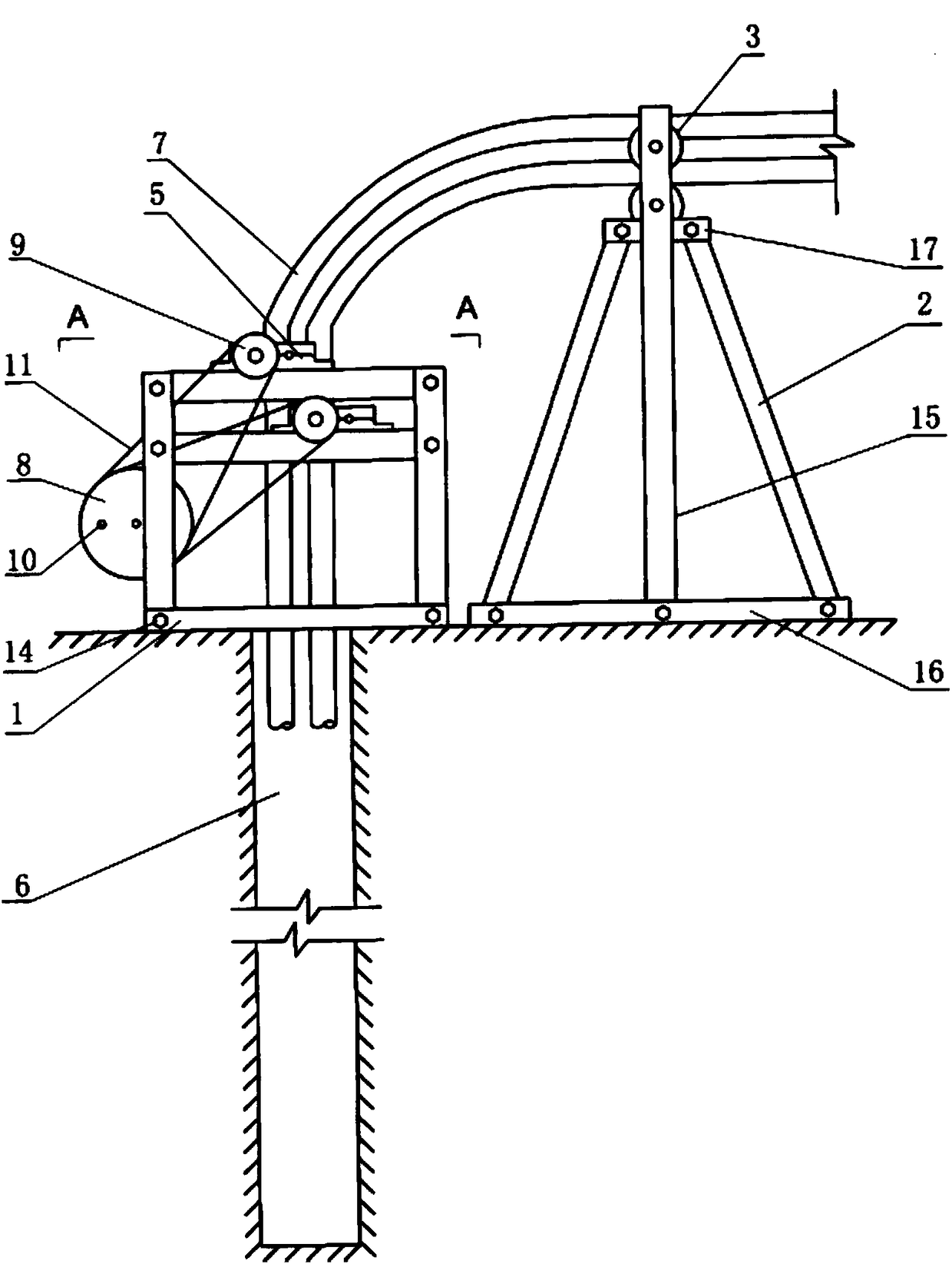
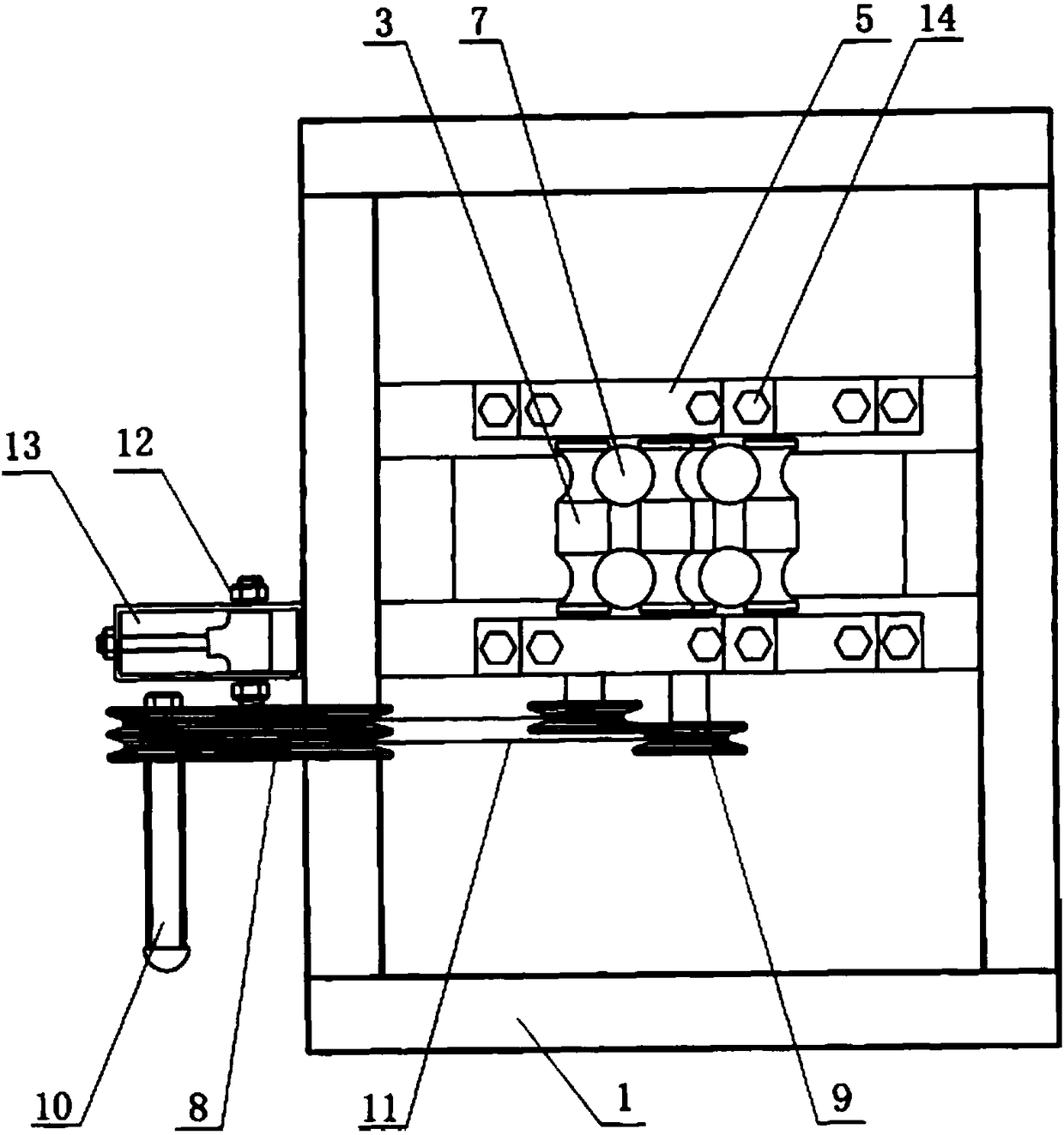
[0020] Such as figure 1 , 2 As shown in , 3, a ground source heat pump installation auxiliary device is mainly composed of a bracket 1, an arc groove roller shaft 3, a handle 10, a driving wheel 8, a driven wheel 9, a support frame and the like. The bracket 1 is made of angle steel, and is assembled into a detachable bracket by bolts and nuts 14, and its height is 800 mm. In the middle of the upper end of the bracket 1, it is divided into upper and lower layers, and two angle steels are fixed by bolts and nuts 14 respectively. The length of the shaft 3 is determined, and holes are respectively arranged in the middle of the opposite inner surfaces of the four angle steels. There are two pairs (i.e. 4) of arc groove roller shafts 3, each of which is formed by round steel at both ends of the roller shaft 3 with concave arc grooves, and is provided with thread. The size and spacing of the arc grooves at both ends are determined according to the outer diameter of the straight p...

Embodiment 2

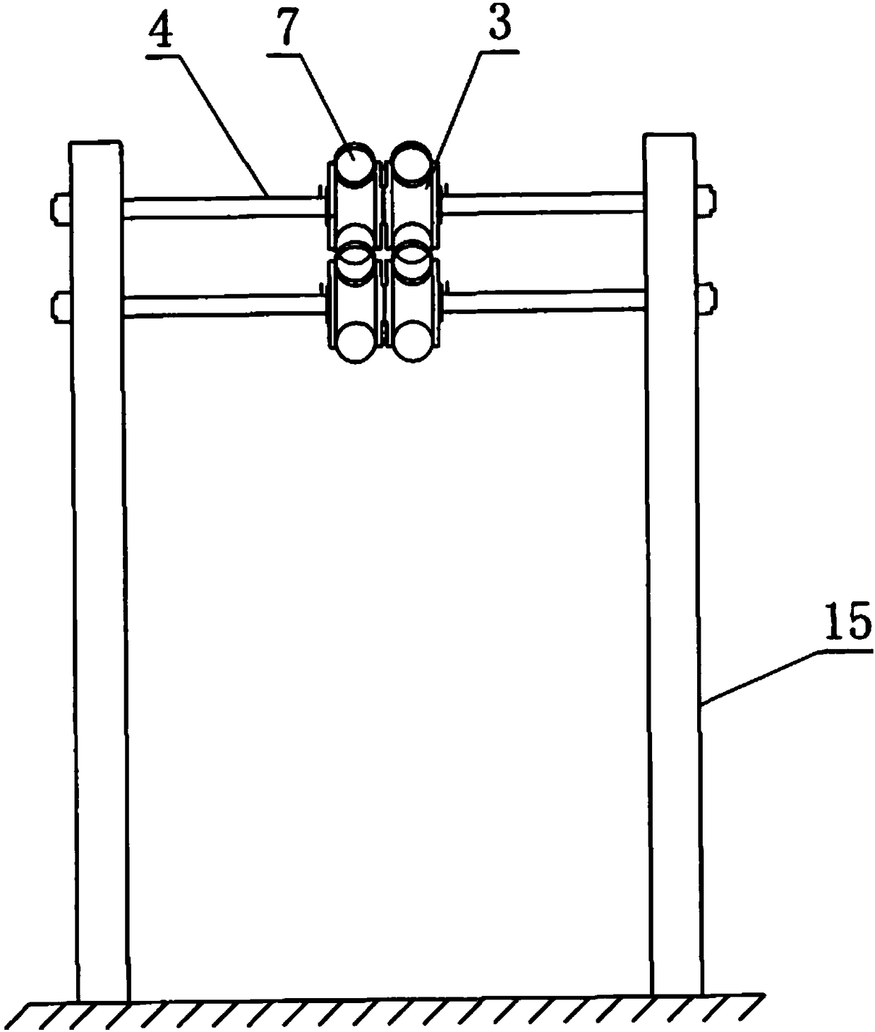
[0022] An auxiliary device for installing a ground source heat pump is the same as in Embodiment 1, and is characterized in that the height of the bracket 1 is 900 mm. The spacing between the upper and lower layers of angle steel of support 1 is 90mm. The driven wheel 9 is 50mm in diameter, and the driving wheel 8 is 160mm in diameter. The height of the two straight columns 15 is 1450 mm, the distance between them is 450 mm, and the distance between the two circular through holes at the top of the two straight columns 15 is 90 mm. The length of the angle steel cross-arm 17 welded respectively on the top of the straight post 15 (i.e. below the through hole) is 10mm.

Embodiment 3

[0024] An auxiliary device for installing a ground source heat pump is the same as that in Embodiment 1, and the feature is that the height of the bracket 1 is 700mm. The spacing between the upper and lower layers of angle steel of the support 1 is 70mm. The driven wheel 9 is 70mm in diameter, and the driving wheel 8 is 140mm in diameter. The height of the two straight columns 15 is 1400 mm, the distance between them is 400 mm, and the distance between the two circular through holes at the top of the two straight columns 15 is 70 mm. The length of the angle steel cross-arm 17 welded respectively on the top of the straight post 15 (i.e. below the through hole) is 7mm.


PUM


Abstract

The invention provides a ground source heat pump mounting auxiliary device, and relates to an auxiliary device for vertical burying of a ground source heat pump underground heat exchanger. The groundsource heat pump mounting auxiliary device is mainly composed of a bracket, an arc groove roller shaft, a handle, a driving wheel, a driven wheel, a supporting frame and the like. The ground source heat pump mounting auxiliary device can increase the burying speed of the ground source heat pump underground heat exchanger, can ensure the construction quality, and further has the characteristics ofbeing in simple in operation, capable of saving energy, convenient to operate in a field, low in cost, convenient to apply and popularize and the like. The ground source heat pump mounting auxiliary device can be widely applied to vertical burying of the ground source heat pump underground heat exchangers all over the country.

Description

technical field [0001] The invention belongs to the technical field of installation of a ground source heat pump system, and in particular relates to a ground source heat pump installation auxiliary device. Background technique [0002] According to incomplete statistics, my country's building energy consumption has reached 27.5% of the total energy consumption at present, and this figure will continue to increase with the rapid development of China's construction industry. Therefore, with the establishment of the basic national policy of energy conservation and emission reduction, the development of building energy conservation work is even more significant. According to the country's goal of achieving 65% energy saving in buildings, in addition to improving building enclosures to achieve energy savings of 30% to 35%, energy-consuming equipment and systems must also achieve energy savings of more than 30%. The use of renewable energy can undoubtedly effectively achieve ene...

Claims


Application Information

Patent Timeline
Patent Type & Authority Applications(China)
IPC IPC(8): F25B30/06
CPCF25B30/06
Inventor 曲滨
Owner 山东一源能源科技开发有限公司
Why Eureka
Try Eureka