Particulate matter sampling rotating shaft inner runner system

A technology of inner flow channel and particulate matter, which is applied in the field of particle detection, can solve the problems that the movement and measuring chamber cannot rotate freely, cannot use the movement reasonably and effectively, and affect the operation of components, etc., to achieve a simple and beautiful exterior of the product and light weight , the effect of improving quality

Pending Publication Date: 2018-05-29
深圳市翠云谷科技有限公司
View PDF10 Cites 0 Cited by
  • Summary
  • Abstract
  • Description
  • Claims
  • Application Information

AI Technical Summary

Problems solved by technology

[0004] Those skilled in the art have analyzed the defects of the existing known technologies. If based on the principle of light scattering, the jet pump is used as the air drainage source to continuously introduce industrial exhaust gas into the measurement chamber, so that the entire device forms a continuous loop. How to design this circuit has become a very important link in product design. However, the existing measuring devices do not have a specific technical solution to achieve the desired effect. The system, however, needs to be disassembled during device maintenance, and the flow path is additionally disconnected. The movement and the measurement chamber cannot be freely rotated in and out, resulting in inconvenient operation; in addition, the movement cannot be used reasonably and effectively due to the non-circulatory passage of the gas entering , rotating shaft, rotating shaft fixing seat and other components, not only that, but even affect the operation of these components

Method used


Image

  • Particulate matter sampling rotating shaft inner runner system

Examples


Embodiment 1

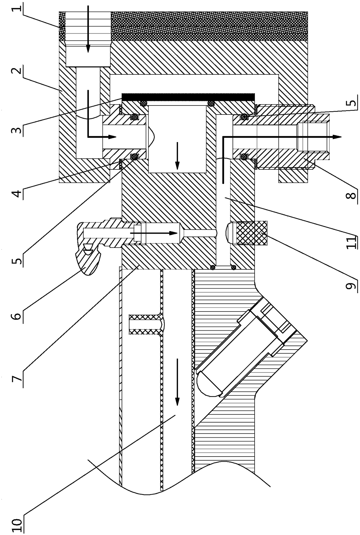
[0035] like figure 1 As shown, the purpose of the technical means implemented in the particle sampling rotating shaft inner channel system described in Embodiment 1 of the present invention is to solve the problem that the rotating shaft of the traditional detection device cannot rotate freely during installation and maintenance, and cannot reach the gas In the state of normal circulation, the problem closely related to installation and maintenance is that if it is implemented according to the structure of the traditional detection device, it needs to be disassembled and the flow path is disconnected during maintenance. Therefore, the technical solution adopted to solve the technical problem includes the shaft seat 2, and the movement 7 that is movably installed on the rotating shaft seat 2 through the corresponding shaft core assembly.

[0036] Analyze the structure between the above-mentioned rotating shaft seat 2 and the rotating shaft assembly:

[0037] The implemented sh...

Embodiment 2

[0048] like figure 1 As shown, the particle sampling shaft inner runner system described in Embodiment 2 of the present invention is a modification based on the technical solution implemented in Embodiment 1, and a supply air supply is formed between the implemented measurement chamber 10 and the external exhaust gas environment. On the basis of the continuous gas circulation channel of the exhaust gas to be measured, a section of gas passage is added between the measurement chamber 10 and the horizontal flow channel 11, so that the measured exhaust gas is discharged along the horizontal flow channel 11 and the vertical flow channel of the lower shaft core 8 to the outside, thus forming two upper and lower circulation flow channel units inside the system, that is, the implemented air intake channel, the vertical flow channel of the upper shaft core, the air intake chamber and the measurement chamber 10 constitute the upper circulation inner flow channel unit that allows the gas...


PUM


Abstract

The invention relates to a particulate matter sampling rotating shaft inner runner system. The inner runner system comprises a gas inlet duct, an upper vertical runner, a gas inlet cavity and a lowervertical runner, wherein the gas inlet duct is formed in one side end surface of a rotating shaft base, the upper vertical runner is formed in an upper shaft core, the two ends of the upper vertical runner communicate with the gas inlet duct and the gas inlet cavity in a machine core, an inner gas channel is formed between the gas inlet cavity and a measuring chamber, and the lower vertical runneris formed in a lower shaft core so as to enable redundant gas inside the machine core to be discharged to the outside. According to the inner runner system, consistent inner gas runners are designedby reasonably utilizing corresponding parts of a rotating shaft so that waste gas to be detected can be continuously recycled between the measuring chamber and an external waste gas environment, and therefore a flow path can be greatly simplified, dismounting is not needed in the maintenance process, the machine core and the measuring chamber can freely rotate to enter and exit a box body withoutdisconnecting the flow path, the structure is compact, the design is reasonable, and the space can be saved; and meanwhile, the appearance of a product can be more concise and attractive, and the requirements of personalized and diversified development directions of modern machinery design products can be met.

Description

technical field [0001] The invention relates to the technical field of particle detection, in particular to a flow channel system in a particle sampling rotating shaft. Background technique [0002] At present, in the field of particle detection technology at home and abroad, according to the different physical measurement mechanisms, it can be divided into sampling method and non-sampling method. Considering the requirements of continuous analysis and long-term online monitoring, light scattering method is a continuous sampling method. It can meet the data volume requirements in the production process of factories involved in exhaust emissions, and is more in line with the conditions of industrial mass production operation from the perspectives of safety and structural equipment manufacturing costs. [0003] The general principle of the light scattering method is that when the floating dust supplied to the darkroom or closed chamber is irradiated with light, under the condi...

Claims


Application Information

Patent Timeline
Patent Type & Authority Applications(China)
IPC IPC(8): G01N1/22G01N15/06
CPCG01N1/22G01N15/06G01N2015/0693
Inventor 黄红明
Owner 深圳市翠云谷科技有限公司
Why Eureka
Try Eureka