Regeneration valve, multi-union valve, hydraulic system and engineering machinery

A regeneration valve, hydraulic fluid technology, applied in the direction of fluid pressure actuating system components, mechanical equipment, fluid pressure actuating devices, etc., can solve the problems of complex structure of the main control valve, achieve simple structure, reduce pressure drop, simplify effect of structure

Pending Publication Date: 2022-02-18
XCMG CONSTR MACHINERY
View PDF0 Cites 1 Cited by
  • Summary
  • Abstract
  • Description
  • Claims
  • Application Information

AI Technical Summary

Problems solved by technology

[0013] The present invention aims to provide a regenerative valve, multi-valve, hydraulic system and engineering machinery, so as to improve the complex structure of the main control valve of the hydraulic system that controls the main hydraulic actuator in the related art

Method used


Image

  • Regeneration valve, multi-union valve, hydraulic system and engineering machinery
  • Regeneration valve, multi-union valve, hydraulic system and engineering machinery
  • Regeneration valve, multi-union valve, hydraulic system and engineering machinery

Examples


Embodiment Construction

[0052] The following will clearly and completely describe the technical solutions in the embodiments of the present invention with reference to the accompanying drawings in the embodiments of the present invention. Obviously, the described embodiments are only some, not all, embodiments of the present invention. The following description of at least one exemplary embodiment is merely illustrative in nature and in no way taken as limiting the invention, its application or uses. Based on the embodiments of the present invention, all other embodiments obtained by persons of ordinary skill in the art without creative efforts fall within the protection scope of the present invention.

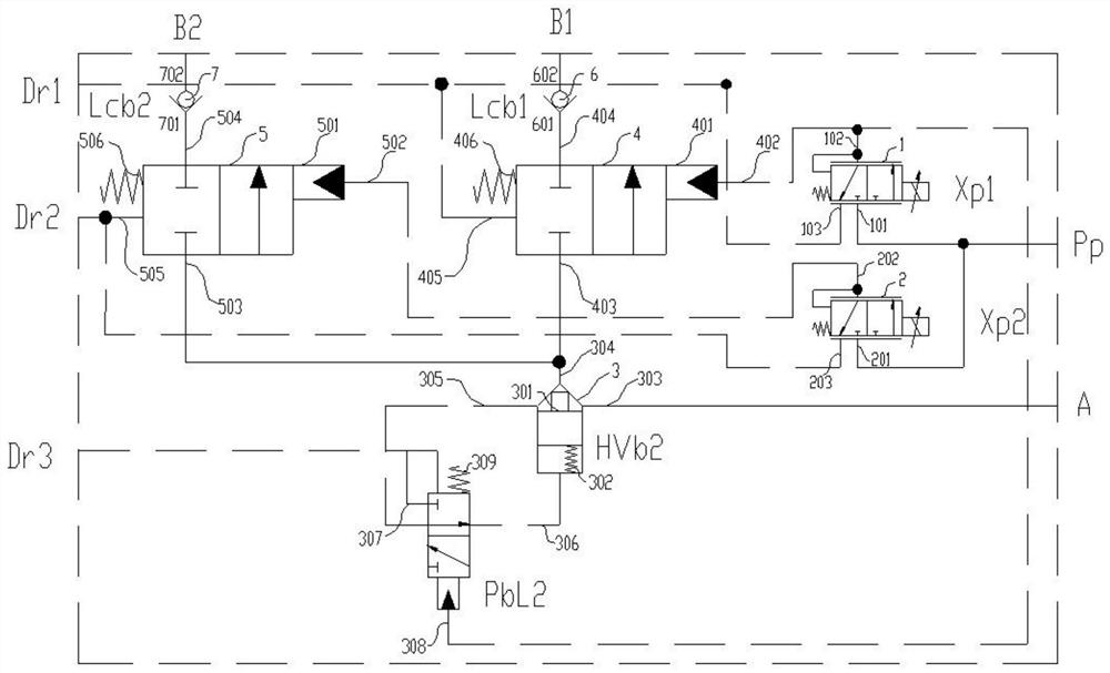
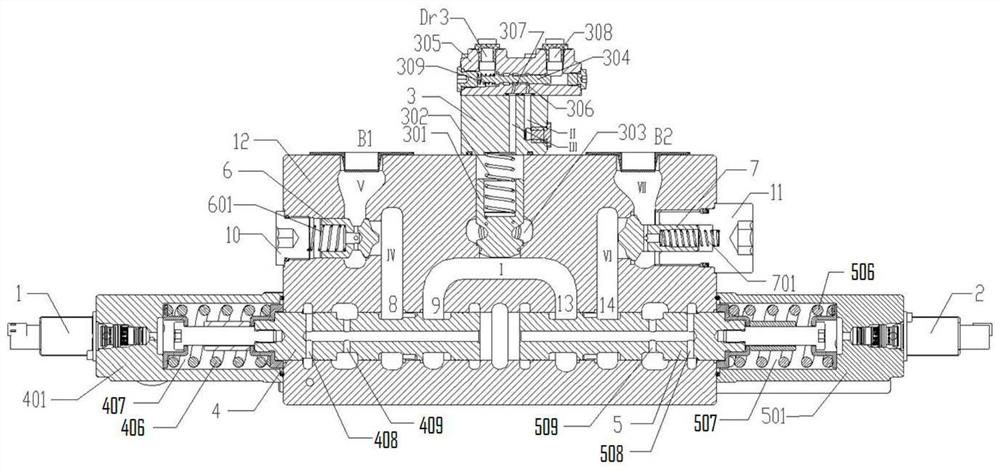
[0053] combine figure 1 and figure 2 As shown, the active valve in this embodiment includes a regeneration valve body 12 , a load holding valve 3 , a first control valve 4 and a first solenoid valve 1 .

[0054] Wherein, the load holding valve 3 includes a first one-way valve 301, a holding valve ...


PUM


Abstract

The invention relates to a regeneration valve, a multi-gang valve, a hydraulic system and engineering machinery. The regeneration valve comprises a regeneration valve body, a load holding valve, a first control valve and afirst electromagnetic valve ; the load holding valve comprises a first one-way valve, a holding valve inlet which is communicated with the outlet end of the first one-way valve and is formed in the regeneration valve body, and a holding valve control fluid port which is used for introducing hydraulic fluid which enables the first one-way valve to be reversely conducted; the first control valve comprises a first control valve cavity, a first control valve core, a first control valve inlet, a first control valve outlet and a first control valve control fluid inlet which are arranged on the regeneration valve body; the first electromagnetic valve comprises a first electromagnetic valve inlet and a first electromagnetic valve outlet, and the first electromagnetic valve outlet is respectively communicated with the first control valve control fluid inlet and the holding valve control fluid inlet; and the first one-way valve cavity extends inwards from the first surface of the regeneration valve body, the first control valve cavity extends inwards from the second surface of the regeneration valve body, and the first surface intersects with the second surface.

Description

technical field [0001] The invention relates to the field of engineering equipment, in particular to a regeneration valve, a multi-valve, a hydraulic system and engineering machinery. Background technique [0002] The hydraulic excavator is a widely used engineering machinery. The structure of the excavator mainly includes getting off the car, the slewing device and the working device. The working device of the hydraulic excavator includes the boom spool, the arm spool, the bucket spool and the corresponding executive body. Since the actuator of the hydraulic excavator has to undergo a reciprocating motion in each working cycle, and the boom and the arm require high pressure and large flow, the boom and the bucket consume most of the energy of the hydraulic excavator. The sum of the consumed system energy exceeds 50% of the total output energy of the main pump. Ordinary hydraulic excavators do not make use of the energy when the boom is lowered and the arm is retracted, wh...

Claims


Application Information

Patent Timeline
Patent Type & Authority Applications(China)
IPC IPC(8): F15B13/02F15B21/00
CPCF15B13/027F15B13/02F15B21/00
Inventor 刘威肖刚彭乐乐
Owner XCMG CONSTR MACHINERY
Why Eureka
Try Eureka