
Fallen leaf cleaning device used for garden lawn

A technology for cleaning devices and lawns, applied in watering devices, lawn growth, gardening, etc., can solve the problems of reduced work efficiency, small cleaning and collection volume, and flammability in case of fire, so as to increase work efficiency, improve collection capacity, and improve The effect of the collection effect

Inactive Publication Date: 2018-06-01
毛渊
View PDF0 Cites 11 Cited by
  • Summary
  • Abstract
  • Description
  • Claims
  • Application Information

AI Technical Summary

Problems solved by technology

[0002] As the temperature drops, trees in gardens in urban areas in northern my country begin to shed their leaves in large numbers. Defoliation is a natural phenomenon. Generally, in autumn, most deciduous plants and trees begin to shed their leaves. The leaves are yellow and curled and fall from the trees. If it is disposed of in time, it is easy to mix with daily garbage to form a "hygienic dead corner", which brings inconvenience to sanitation work. In addition, the weather is dry in autumn and winter, and dead leaves not only affect the appearance, but also are flammable in case of fire, which is easy to cause fire
[0003] The workload of cleaning the fallen leaves is relatively large, and it is usually impossible to clean the fallen leaves in time when the number of sanitation personnel is insufficient. The cleaning and collection volume of the common fallen leaf cleaning device is small, and the collection tank needs to be dumped many times, thereby reducing work efficiency

Method used


Image

  • Fallen leaf cleaning device used for garden lawn
  • Fallen leaf cleaning device used for garden lawn
  • Fallen leaf cleaning device used for garden lawn

Examples


Embodiment Construction

[0018] The following will clearly and completely describe the technical solutions in the embodiments of the present invention with reference to the accompanying drawings in the embodiments of the present invention. Obviously, the described embodiments are only some, not all, embodiments of the present invention. Based on the embodiments of the present invention, all other embodiments obtained by persons of ordinary skill in the art without making creative efforts belong to the protection scope of the present invention.

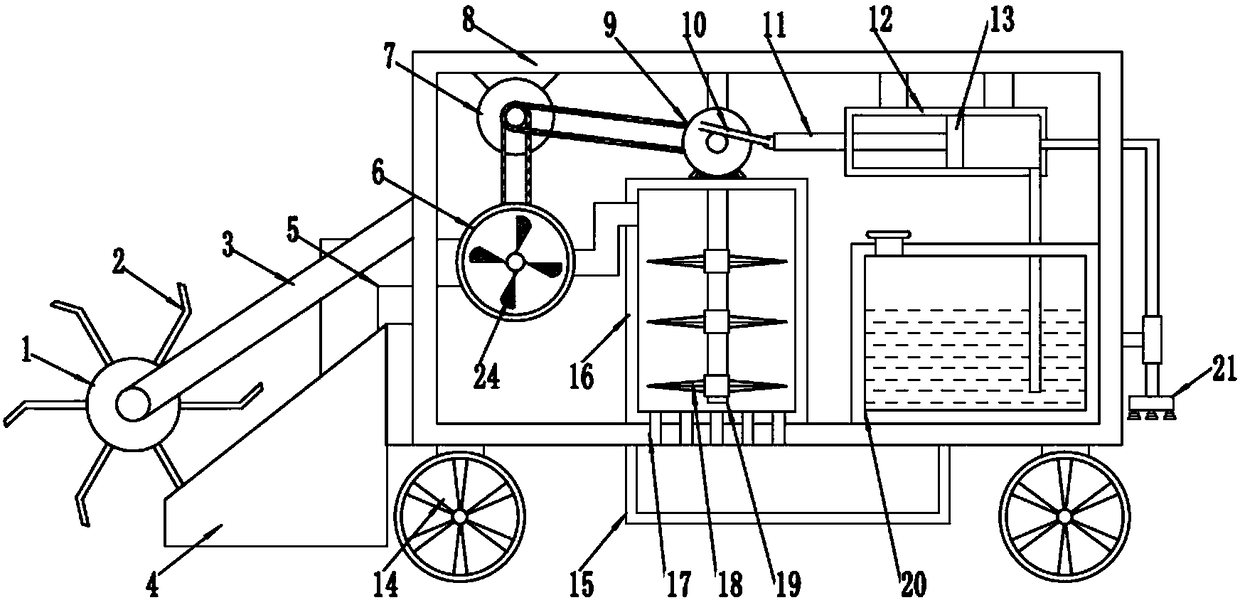
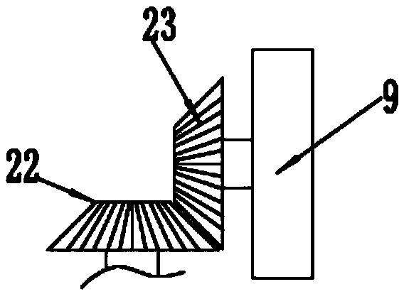
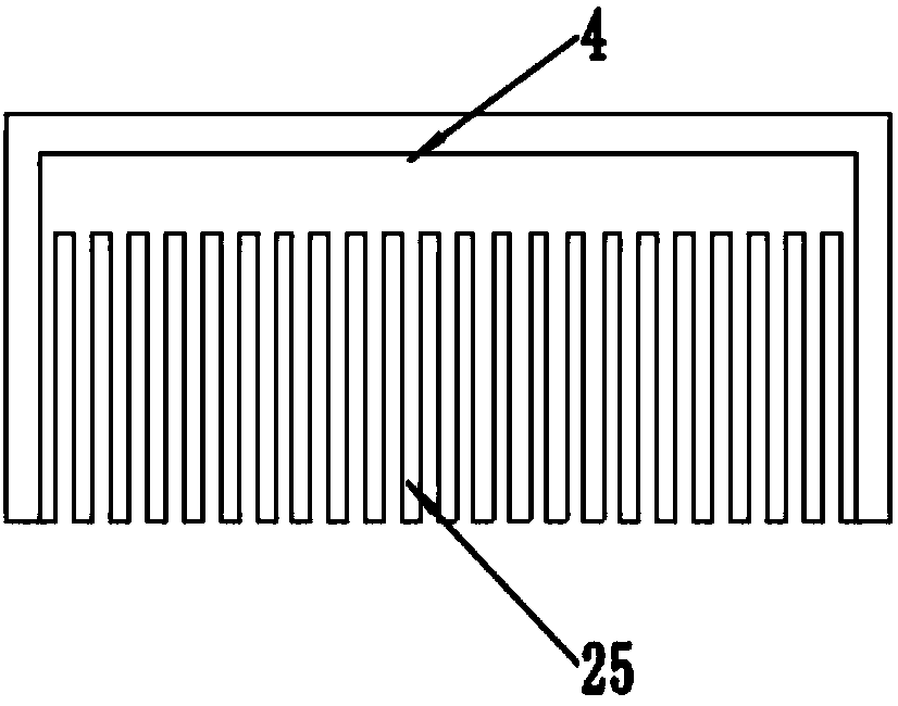
[0019] see Figure 1~3 , a garden and lawn deciduous cleaning device, comprising a bucket 4, a rotating motor 7, a housing 8, a cylinder 12, a crushing chamber 16 and a water tank 20; the left end of the housing 8 is fixedly equipped with a bucket 4, and the bucket The front end of 4 is provided with shovel tooth 25, and shovel tooth 25 is made up of a plurality of alternate poles, and shovel tooth 25 can reduce the damage that bucket 4 causes to lawn, and the...


PUM


Abstract

The invention discloses a fallen leaf cleaning device used for a garden lawn. The fallen leaf cleaning device comprises a bucket, a rotation motor, a shell, a cylinder body, a smashing cavity and a water tank, wherein the left end of the shell is fixedly provided with the bucket; the front end of the bucket is provided with form relieved teeth; a roller is arranged above the bucket; the inner sideof the shell is provided with the rotation motor; a suction fan is arranged below the rotation motor; a fan blade arranged on the inner side of the suction fan is rotatably connected with the outputshaft of the rotation shaft through a belt; the left end of the suction fan is communicated with one end of a leaf feeding pipe; the smashing cavity is arranged on the right of the suction fan; the suction fan is communicated with the smashing cavity through a conduit; the bottom of the smashing cavity is communicated with a collection groove through material falling holes. The fallen leaf cleaning device has a novel design, fallen leaves on the lawn can be stirred to the bucket through an arranged stirring claw, the collection effect of the bucket is improved, the fallen leaves are smashed and collected through the arranged smashing cavity, the smashed fallen leaves occupy a small area so as to improve the collection capacity of the fallen leaves, and the fallen leaf cleaning device has high practicality and is worth popularizing.

Description

technical field [0001] The invention relates to a garden instrument, in particular to a leaf cleaning device for garden lawns. Background technique [0002] As the temperature drops, trees in gardens in northern urban areas of my country begin to shed their leaves in large numbers. Defoliation is a natural phenomenon. Generally, in autumn, most deciduous plants and trees begin to shed their leaves. The leaves are yellow and curled and fall from the trees. If it is disposed of in time, it is easy to mix with daily garbage to form a "hygienic dead corner", which brings inconvenience to sanitation work. In addition, the weather is dry in autumn and winter, and dead leaves not only affect the appearance, but also are flammable in case of fire, which is easy to cause fire. [0003] The workload of cleaning the fallen leaves is relatively large, and it is usually impossible to clean the fallen leaves in time when the number of sanitation personnel is insufficient. The cleaning and ...

Claims


Application Information

Patent Timeline
Patent Type & Authority Applications(China)
IPC IPC(8): A01G20/43A01G25/09
CPCA01G25/09
Inventor 毛渊
Owner 毛渊
Learn More