Trolley for medical apparatus and instruments of orthopedics department

A technology of medical devices and trolleys, applied in the field of medical devices, can solve problems such as inconvenient use, heavy trolleys, and incomplete functions, and achieve the effects of easy disassembly, simple structure, and hand-slip prevention

Inactive Publication Date: 2018-06-01
山东圣腾酒店管理有限公司
0 Cites 1 Cited by

AI-Extracted Technical Summary

Problems solved by technology

After years of accumulation, the technical level and service quality of domestic enterprises have improved, and they have established certain core competitiveness in some subdivided fields, and initially have the strength to break through from low-end to mid-to-high end. Cont...

Method used

Described casing 1 bottom is connected with universal wheel 6 by rotating shaft, and the number of described universal wheel 6 is four, convenient to move, and the number of described fastening nut 13 is two, and the The fastening nut 13 is covered with a rubber sleeve to protect the hands. The handle 14 is provided with anti-slip lines to prevent hand slipping. The first drawer 2, the second drawer 3 and the third drawer 4 are All are provided with a handle 7, and the handle 7 is provided with a non-slip texture, so that the drawer is easy to open.
Principle of work of the present invention: during use, according to the operator's height, adjust the fastening nut 13 between the hollo...

Abstract

The invention relates to a trolley for medical apparatus and instruments of the orthopedics department. The trolley comprises a box body. Universal wheels are arranged at the bottom of the box body. Afirst drawer, a second drawer and a third drawer are arranged on one side of the box body from bottom to top in sequence. Dry ice is arranged at the bottom of the first drawer, activated carbon is arranged on the bottom layer of the second drawer, pulleys are arranged at the bottoms of the first drawer, the second drawer and the third drawer separately, and sliding grooves are connected to the bottoms of the pulleys and fixed to the inner side of the box body. An article holding table is arranged on the top of the box body, magnets are arranged at the bottom of the article holding table, a test tube placing table is arranged in the article holding table, and a case clip is arranged at the bottom of the article holding table. A fence is arranged around the top of the article holding table,an LED lamp is arranged at the upper end of one side of the fence, and a trolley armrest is arranged at one end of the box body and composed of a hollow rod and a solid rod. The trolley has more complete functions, and more convenience is provided for nurses during using.

Application Domain

DiagnosticsAmbulance service +1

Technology Topic

HandrailTest tube +7

Image

  • Trolley for medical apparatus and instruments of orthopedics department
  • Trolley for medical apparatus and instruments of orthopedics department

Examples

  • Experimental program(1)

Example Embodiment

[0015] The preferred embodiments of the present invention will be described below in conjunction with the accompanying drawings. It should be understood that the preferred embodiments described here are only used to illustrate and explain the present invention, and are not intended to limit the present invention.
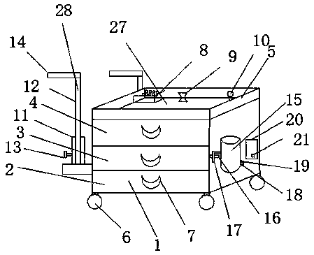
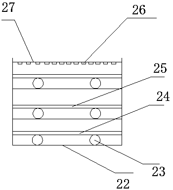
[0016] like Figure 1-Figure 2 As shown, a trolley for orthopedic medical equipment includes a box body 1, the bottom of the box body 1 is provided with universal wheels 6, and one side of the box body 1 is sequentially provided with a first drawer 2, The second drawer 3 and the third drawer 4, the bottom of the first drawer 2 is provided with dry ice 24, the bottom of the second drawer 3 is provided with activated carbon 25, the bottom of the first drawer 2, the second drawer 3 and the bottom of the third drawer 4 are provided with There is a pulley 23, the bottom of the pulley 23 is connected with a chute 22, and the chute 22 is fixed on the inside of the box body 1, the top of the box body 1 is provided with an article holding platform 27, and the bottom of the article holding platform 27 is provided with Magnet 26, described article holding platform 27 is provided with test tube placing platform 8, and described test tube placing platform 8 side is provided with case clip 9, and described article holding platform 27 top is provided with fence 5 around, and described fence 5 The upper end of one side is provided with an LED lamp 10, and one end of the box body 1 is provided with a trolley handrail 28, and the trolley handrail 28 is composed of a hollow rod 11 and a solid rod 12, and one side of the hollow rod 11 is threaded. There is a fastening nut 13, and one end of the fastening nut 13 runs through the hollow rod 11, the hollow rod 11 and the solid rod 12 are flexibly connected by the fastening nut 13, and a trolley is arranged on the top of the solid rod 12 The handle 14, the other end of the box body 1 is provided with a battery 20, the side of the battery 20 is provided with a charging socket 21, the LED lamp 10 is connected to the battery 20 through a wire, and a trash can 15 is provided on one side of the battery 20, One side of the bottom of the garbage can 15 is provided with a water outlet 18, the top of the water outlet 18 is provided with a valve 19, the side of the garbage can 15 is provided with a hook 17, the casing 1 is provided with a sleeve 16, and the The hook 17 is movably connected to the sleeve 16.
[0017] The bottom of the box body 1 is connected with a universal wheel 6 through a rotating shaft, and the number of the universal wheels 6 is four, which is convenient to move. The number of the fastening nuts 13 is two, and the fastening nuts 13 are two. The nut 13 is covered with a rubber sleeve, which acts as a hand protector. The handle 14 is provided with anti-slip lines to prevent hand slipping. The first drawer 2, the second drawer 3 and the third drawer 4 are all provided with Handle 7, the handle 7 is provided with non-slip texture, the drawer is easy to open.
[0018] The working principle of the present invention: when in use, the fastening nut 13 between the hollow rod 11 and the solid rod 12 is adjusted according to the height of the operator to adjust the height of the cart armrest, and four universal wheels 6 are set at the bottom of the box body 1 to make the cart It is easy to move, and the connection between the trash can 15 and the box body 1 through the hook 17 and the sleeve 16 makes it easy to disassemble the trash can 15. By setting dry ice 24 at the bottom of the first drawer 2, the medicines that require temperature can be refrigerated. Activated carbon 25 is set at the bottom of the second drawer 3 and can play a cleaning and disinfection effect, and magnet 26 can be played to absorb iron surgical tools by setting magnet 26 at the bottom of article holding platform 27 .
[0019] The above are the preferred embodiments of the present invention, and those skilled in the art of the present invention can also change and modify the above-mentioned embodiments. Therefore, the present invention is not limited to the above-mentioned specific embodiments. Any obvious improvements, substitutions or variations made on the basis of the above-mentioned methods belong to the protection scope of the present invention.

PUM

no PUM

Description & Claims & Application Information

We can also present the details of the Description, Claims and Application information to help users get a comprehensive understanding of the technical details of the patent, such as background art, summary of invention, brief description of drawings, description of embodiments, and other original content. On the other hand, users can also determine the specific scope of protection of the technology through the list of claims; as well as understand the changes in the life cycle of the technology with the presentation of the patent timeline. Login to view more.

Similar technology patents

Body condition measuring device

InactiveUS20050234351A1simple structure
Owner:DENSO CORP

Magnetic cooling apparatus and control method thereof

ActiveUS20130180263A1simple structure
Owner:SAMSUNG ELECTRONICS CO LTD

Dual-Drivetrain of Power-Assist Vehicle

InactiveUS20100181130A1enhance uphill momentumsimple structure
Owner:CHOU WEN CHENG

Classification and recommendation of technical efficacy words

  • Simple structure
  • reasonable design

Sharing system for air-conditioning coat

InactiveCN107440179ASimple structureeasy to wear
Owner:QINGDAO HAIER AIR CONDITIONER GENERAL CORP LTD

Feeding device of sorter of batteries plate

InactiveCN101357717ASimple structurecooperate well
Owner:NANJING NORMAL UNIVERSITY

Emergency parachuting device and method for multiple-rotor unmanned aerial vehicle

InactiveCN103895870Aavoid aircraft crashSimple structure
Owner:SOUTH CHINA AGRI UNIV +1

Embedding accuracy control construction method for embedded part of overlong equipment foundation platform

InactiveCN102134879Areasonable designSimple construction steps
Owner:SCEGC NO 6 CONSTR ENG GRP CO LTD
Why Eureka
Try Eureka