Laser engraving device

A technology of laser engraving and chute, which is applied in the direction of auxiliary devices, laser welding equipment, auxiliary welding equipment, etc., can solve the problems of poor engraving effect of the workpiece, and achieve the effect of improving engraving effect and strengthening the limit effect

Inactive Publication Date: 2018-06-01
重庆鑫盟精密模具有限公司
View PDF9 Cites 6 Cited by
  • Summary
  • Abstract
  • Description
  • Claims
  • Application Information

AI Technical Summary

Problems solved by technology

[0004] The present invention intends to provide a laser engraving device to solve the problem that the current laser engraving device does not limit the workpiece and the workpiece engraving effect is not good

Method used


Image

  • Laser engraving device

Examples


Embodiment Construction

[0016] Further detailed explanation through specific implementation mode below:

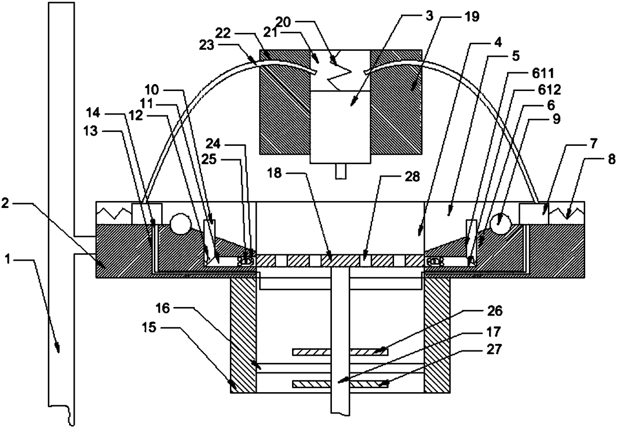
[0017] The reference signs in the drawings of the description include: machine base 1, workbench 2, laser engraving head 3, round hole 4, first chute 5, auxiliary groove 6, vertical groove 611, transverse groove 612, slider 7, First spring 8, circular shaft 9, first wedge block 10, second wedge block 11, second spring 12, through hole 13, steel wire 14, sleeve 15, iron plate 16, threaded rod 17, support plate 18 , auxiliary block 19, the third spring 20, the second chute 21, arc groove 22, elastic iron plate 23, clamping arm 24, the fourth spring 25, upper magnet 26, lower magnet 27, negative pressure hole 28.

[0018] The embodiment is basically as attached figure 1 Shown: laser engraving device, comprise support and auxiliary block 19, workbench 2 is installed on the support, the middle part of workbench 2 offers circular hole 4. The auxiliary block 19 is provided with a second chute 21, the ...


PUM


Abstract

The invention discloses a laser engraving device. The device comprises a machine base, a workbench, a laser engraving head and an adjustable mechanism are arranged on the machine base, and a round hole is formed in the middle of the workbench; first sliding grooves and auxiliary grooves are correspondingly and symmetrically formed in the workbench along the round hole, sliding blocks are slidablyconnected in the first sliding grooves, and first springs are arranged between the sliding blocks and the first sliding grooves; round shafts are rotationally connected in the first sliding grooves; the auxiliary grooves comprise vertical grooves and transverse grooves, first inclined wedge blocks are slidably connected in the vertical grooves, and second inclined wedge blocks are arranged in thetransverse grooves; second springs are arranged between the second inclined wedge blocks and the vertical grooves, and clamping mechanisms are arranged on the second inclined wedge blocks; through holes are formed in the bottoms of the transverse grooves, and steel wires are arranged on the sliding blocks; a sleeve pipe is arranged at the bottom of the workbench, an iron plate is fixedly connectedin the sleeve pipes, a threaded rod is connected to the iron plate in a threaded mode, and the steel wires are fixedly connected with the threaded rod; and a supporting plate is arranged on the threaded rod, and a positioning mechanism is arranged on the threaded rod. The laser engraving device mainly solves the problem that an existing laser engraving device is poor in workpiece engraving effect.

Description

technical field [0001] The invention relates to the technical field of machining with lasers. Background technique [0002] Laser engraving is based on numerical control technology, and laser is the processing medium. The physical denaturation of the instant melting and gasification of the processing material under the irradiation of laser engraving can make laser engraving achieve the purpose of processing. Laser engraving is the use of laser technology to engrave text on objects. The characters engraved by this technology have no notches, the surface of the object is still smooth, and the writing will not wear out. [0003] When the laser engraving device is in use, it is necessary to position the workpiece first, and then perform laser engraving on the workpiece. At present, the laser engraving device mainly places the workpiece in the groove or on the transmission mechanism. Since the workpiece is not limited, the workpiece may shake during laser engraving, which direc...

Claims


Application Information

Patent Timeline
Patent Type & Authority Applications(China)
IPC IPC(8): B23K26/362B23K26/70B23K37/04
CPCB23K26/361B23K26/702B23K37/0435
Inventor 吕献平
Owner 重庆鑫盟精密模具有限公司
Why Eureka
Try Eureka