Auxiliary device and method for assembling belt pulley of engine snubber

An auxiliary device and pulley technology, which is applied to hand-held tools, manufacturing tools, etc., can solve the problems of broken crankshaft small end, high labor intensity, low production efficiency, etc., and achieves improved assembly efficiency, reduced labor intensity, and good practicability. Effect

Pending Publication Date: 2018-06-01
GUANGXI YUCHAI MASCH CO LTD
View PDF8 Cites 1 Cited by
  • Summary
  • Abstract
  • Description
  • Claims
  • Application Information

AI Technical Summary

Problems solved by technology

[0002] At present, in the engine manufacturing industry, especially in the assembly process of large engines, the way to assemble the engine shock absorber pulley on the engine assembly line is generally to manually lift the shock absorber pulley to the rear end of the crankshaft and then assemble it. Generally, the engine shock absorber pulley has It weighs forty or fifty catties, some weigh more than one hundred catties, and some are even heavier. Manual lifting is labor-intensive and production efficiency is low.
Moreover, the connection between the traditional engine damper pulley and the small end of the crankshaft is generally the connection between the keyway and the key. Since the small end of the crankshaft has a key groove, when the power is increased and the torque is increased, the quality failure of the small end of the crankshaft is prone to breakage. To solve the quality fault that the small end of the crankshaft is easy to break, and to enhance the strength of the small end of the crankshaft, the technicians developed a crankshaft without a keyway at the small end of the crankshaft. The connection of the small end of the crankshaft is a keyless connection, which brings great difficulties to the assembly. During assembly, the positioning groove on the inner wheel of the shock absorber is difficult to align with the positioning groove on the small end of the crankshaft, and the production efficiency is low.

Method used


Image

  • Auxiliary device and method for assembling belt pulley of engine snubber
  • Auxiliary device and method for assembling belt pulley of engine snubber
  • Auxiliary device and method for assembling belt pulley of engine snubber

Examples


Embodiment Construction

[0025] The specific embodiments of the present invention will be described in detail below in conjunction with the accompanying drawings, but it should be understood that the protection scope of the present invention is not limited by the specific embodiments.

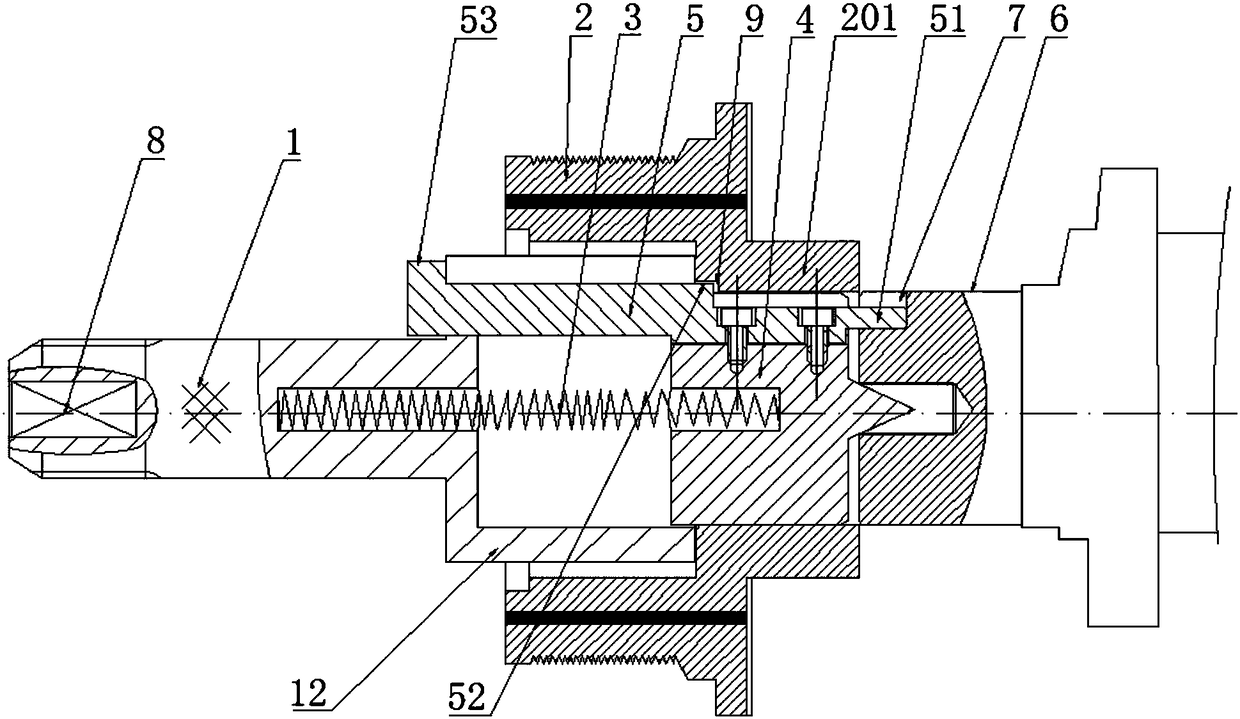
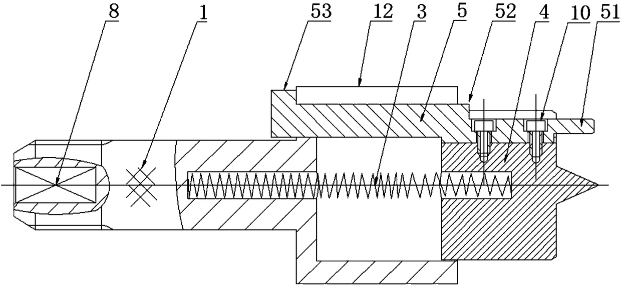
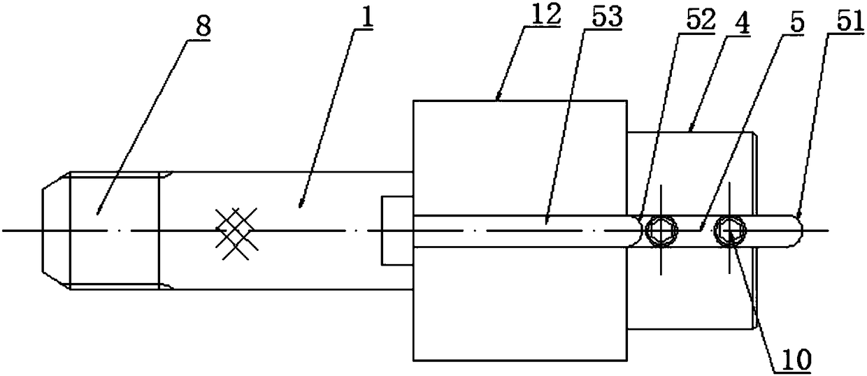
[0026] The specific embodiment of the present invention is like this: as Figure 1-7 As shown, an auxiliary device for engine shock absorber pulley assembly, including a push rod 1, the front end of the push rod 1 is compatible with the rear end of the inner wheel 201 of the pulley 2, and the front end of the push rod 1 is inserted axially. The support shaft 4 that is adapted to the inner hole of the inner wheel 201, the rotating surface of the support shaft 4 is provided with an axially extending clamping block 5, the clamping block 5 is a square bar, and the front and rear ends of the clamping block 5 are respectively provided with The engaging structure that engages the crankshaft positioning groove 7 at the end of ...


PUM


Abstract

The invention discloses an auxiliary device for assembling a belt pulley of an engine snubber. The auxiliary device comprises a push rod; the front end surface of the push rod is matched with the rearend surface of an inner wheel of the belt pulley; a supporting shaft matched with an inner hole of the inner wheel is axially arranged at the front end of the push rod in an inserted mode; a clampingblock which extends in the axial direction is arranged on the rotating surface of the supporting shaft; clamping structures which are in clamping fit with a crankshaft positioning groove formed in the end part of a crankshaft and an inner wheel positioning groove located at the rear end of the inner wheel and corresponding to the crankshaft positioning groove are arranged at the front end and therear end of the clamping block; and a spring reset mechanism for driving the supporting shaft to slide back and forth in the axial direction is arranged between the push rod and the supporting shaft.The invention further discloses a method for assembling the belt pulley of the engine snubber. According to the technical scheme, the auxiliary device and method has the advantages of being reasonable in structural design, easy to manufacture, convenient to carry, good in practicability, simpler in operation, capable of improving the assembling efficiency and capable of facilitating press fitting, and assembling and positioning of the belt pulley are accurate.

Description

technical field [0001] The invention relates to the field of internal combustion engine assembly, more specifically, it relates to an auxiliary device and method for assembling an engine shock absorber pulley. Background technique [0002] At present, in the engine manufacturing industry, especially in the assembly process of large engines, the way to assemble the engine shock absorber pulley on the engine assembly line is generally to manually lift the shock absorber pulley to the rear end of the crankshaft for assembly. Generally, the engine shock absorber pulley has Forty to fifty catties weighed, some weighed more than one hundred catties, and some were even heavier. Manual lifting was labor-intensive and production efficiency was low. Moreover, the connection between the traditional engine damper pulley and the small end of the crankshaft is generally the connection between the keyway and the key. Since the small end of the crankshaft has a key groove, when the power is...

Claims


Application Information

Patent Timeline
Patent Type & Authority Applications(China)
IPC IPC(8): B25B27/02
CPCB25B27/02
Inventor 李旭旺
Owner GUANGXI YUCHAI MASCH CO LTD
Why Eureka
Try Eureka