Method and device for realizing connection of optical transceiver and main printed circuit board

A technology for printed circuit boards and optical transceiver devices, which is applied in the directions of printed circuits connected with non-printed electrical components, and assembling printed circuits with electrical components, which can solve difficult process quality control, low production efficiency and high production costs. problems, to achieve the effect of eliminating randomness and uncertainty, low cost, and reduced production cost

Inactive Publication Date: 2010-02-10
CHENGDU SUPERXON COMM TECH CO LTD
View PDF0 Cites 3 Cited by
  • Summary
  • Abstract
  • Description
  • Claims
  • Application Information

AI Technical Summary

Problems solved by technology

[0004] This method is complex in process, difficult in process quality control, and low in production efficiency. In particular, a precision and special hot-press welding machine must be used, and the production cost is high.

Method used


Image

  • Method and device for realizing connection of optical transceiver and main printed circuit board
  • Method and device for realizing connection of optical transceiver and main printed circuit board
  • Method and device for realizing connection of optical transceiver and main printed circuit board

Examples


Embodiment Construction

[0028] The technical solutions of the present invention will be further described below in conjunction with the accompanying drawings and through specific implementation methods.

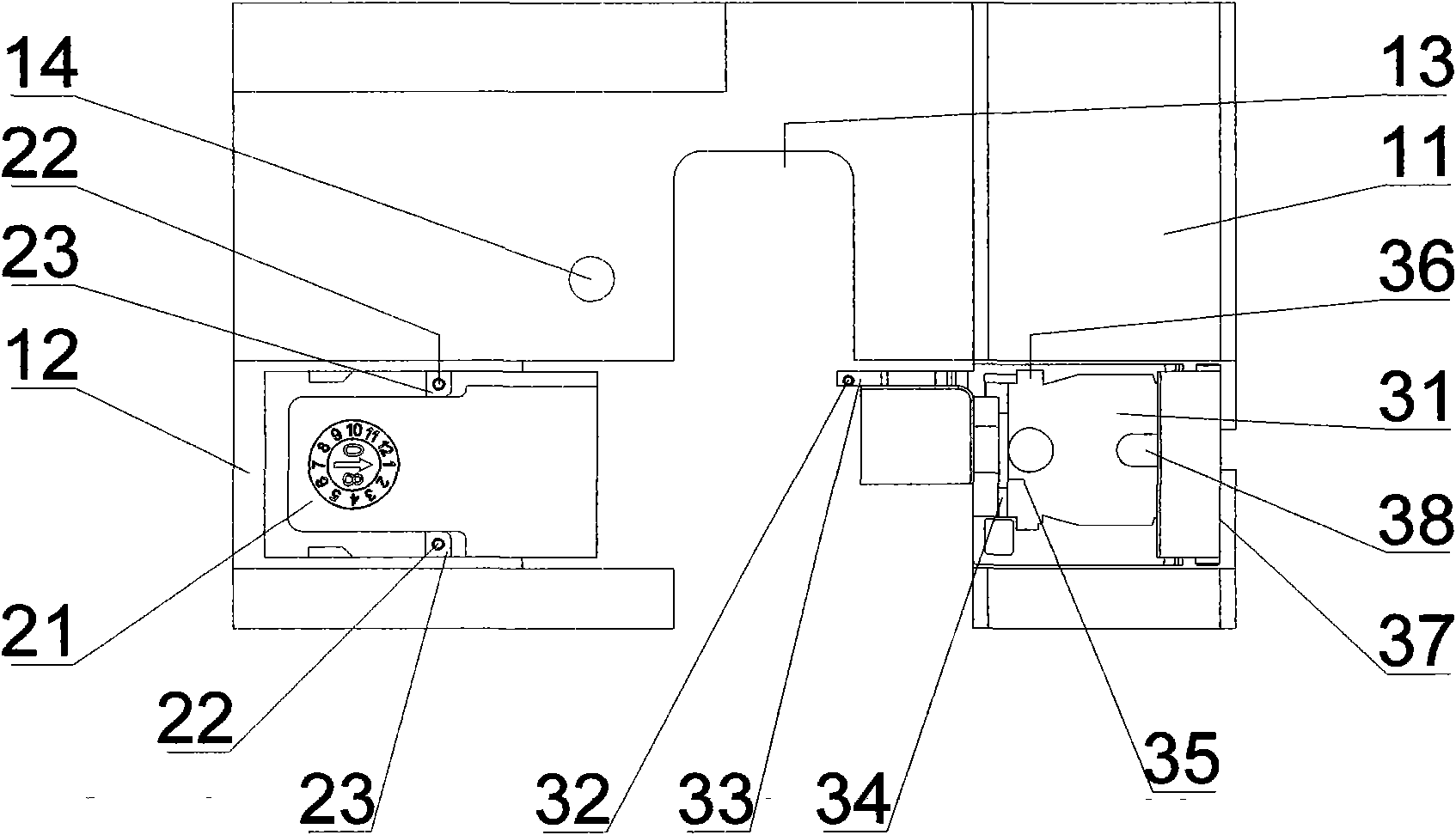
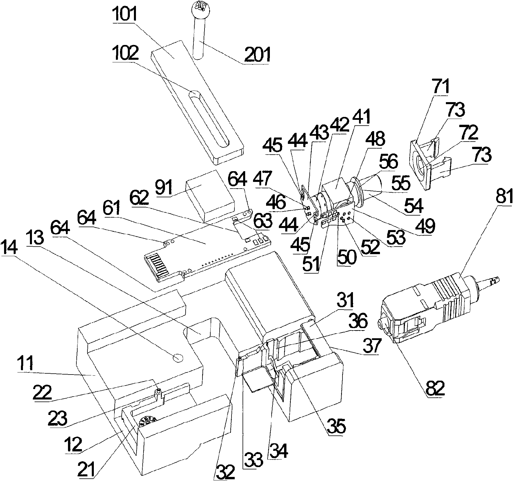
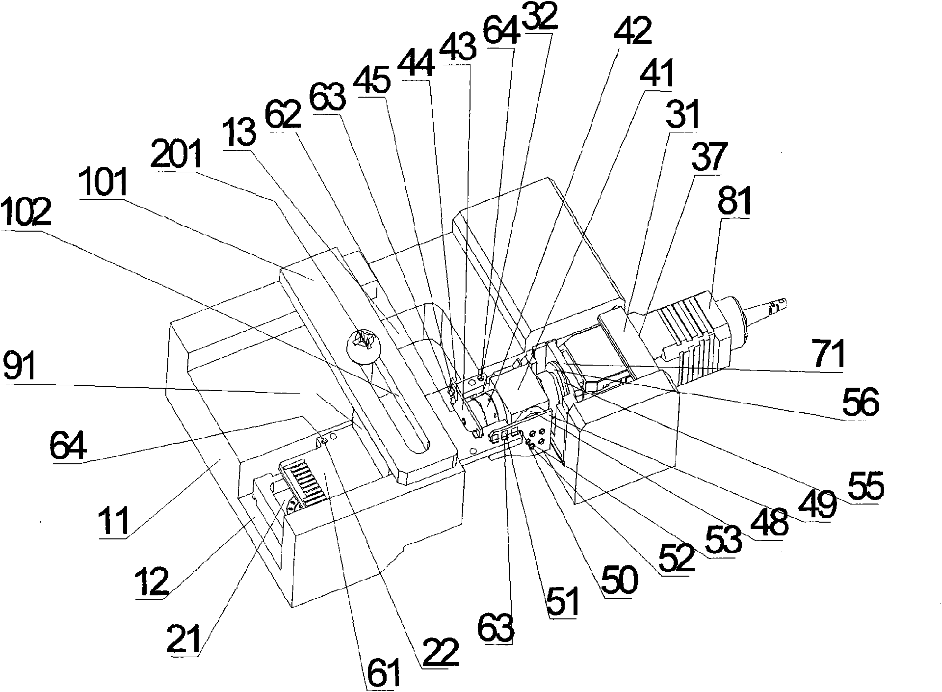
[0029] figure 1 It is a schematic top view of the base in the specific embodiment of the present invention. Such as figure 1 As shown, the base consists of a base table 11 , a rear positioning casting 21 and a front positioning casting 31 .

[0030] The main body of the base platform 11 is a rectangular parallelepiped structure, and a screw hole 14 is arranged near the middle part, and a rectangular slot 12 is arranged near the long side of the base 11 . The metal shell of the optical transceiver module is processed by casting technology. The metal shell of the optical transceiver module is glued in the rectangular groove 12 with super glue, and fixed with the base platform 11 as a whole. From the side of the base platform 11 A notch 13 is machined to cut the metal shell into two sections, a rear...


PUM


Abstract

The invention discloses a method and a device for realizing connection of an optical transceiver and a main printed circuit board. The receiving end pin and the transmitting end pin of the optical transceiver are respectively connected with a bridge connection printed circuit board; the side end of the bridge connection printed circuit board is provided with a U-shaped groove, and welding discs inparallel array distribution are arranged besides the U-shaped groove; one end of the main printed circuit board is provided with a C-shaped opening, and two ends of the C-shaped opening are manufactured with a connecting welding disc; the bridge connection printing circuit boards are inserted into two ends of the C-shaped opening of the main printed circuit board via the U-shaped groove to ensurethat the welding discs in parallel array distribution of the receiving end bridge connection printed circuit boards and the transmitting end bridge connection printed circuit boards are respectivelyaligned with the connecting welding discs on two ends of the C-shaped opening of the main printed circuit board, a base seat positioning component fixes the main printed circuit board, and a pressingcomponent tightly presses the main printed circuit board. The technical scheme of the invention can bring accurate assembly and positioning and reliable connection, greatly improve production efficiency and greatly lower production cost.

Description

technical field [0001] The invention relates to the technical field of optical fiber communication, in particular to a method and a device for realizing the connection between an optical transceiver device and a main printed circuit board. Background technique [0002] At present, in the process of producing optical transceiver modules, there are two methods of assembling and welding optical transceiver devices and main printed circuit boards. One is that the operator uses ordinary tools, such as tweezers, to bend each of the receiving end and the sending end of the optical transceiver device. root metal pins, so that each metal pin is aligned to the corresponding pad on the main printed circuit board, and then the optical transceiver device and the main printed circuit board are assembled into the metal shell of the optical transceiver module, and tinned Solder each metal pin to the corresponding pad on the main printed circuit board. This method has many human factors. Dir...

Claims


Application Information

Patent Timeline
Patent Type & Authority Applications(China)
IPC IPC(8): H05K3/34H05K1/18
Inventor 杨忠
Owner CHENGDU SUPERXON COMM TECH CO LTD
Why Eureka
Try Eureka