Punching machine for integral ceramic fiber module

A ceramic fiber and punching machine technology, which is applied in metal processing and other directions, can solve problems such as punching inclination, product quality is not easy to control, and production efficiency is low.

Inactive Publication Date: 2018-06-01
LUYANG ENERGY SAVING MATERIALS CO LTD
View PDF7 Cites 1 Cited by
  • Summary
  • Abstract
  • Description
  • Claims
  • Application Information

AI Technical Summary

Problems solved by technology

This process method not only has low production efficiency, but also is not easy to control the product quality; it often causes quality problems such as uneven drilling depth and inclined drilling.

Method used


Image

  • Punching machine for integral ceramic fiber module
  • Punching machine for integral ceramic fiber module
  • Punching machine for integral ceramic fiber module

Examples


Embodiment Construction

[0030] In order to make the purpose, technical solutions and advantages of the embodiments of the present invention clearer, the technical solutions in the embodiments of the present invention will be clearly and completely described below in conjunction with the drawings in the embodiments of the present invention. Obviously, the described embodiments It is a part of embodiments of the present invention, but not all embodiments. Based on the embodiments of the present invention, all other embodiments obtained by persons of ordinary skill in the art without making creative efforts belong to the protection scope of the present invention.

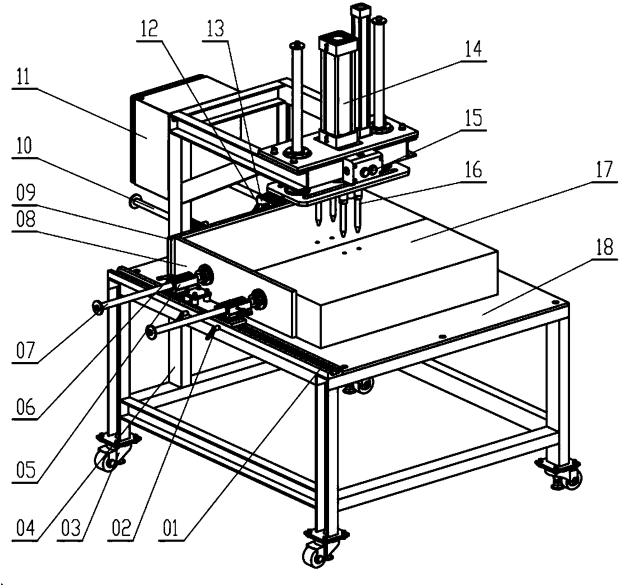
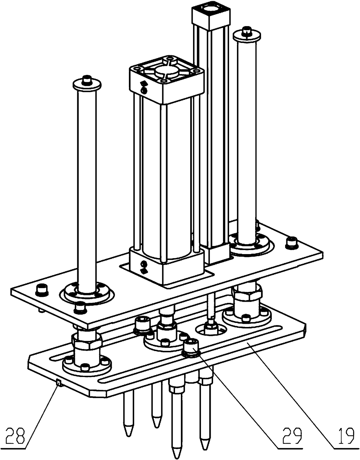
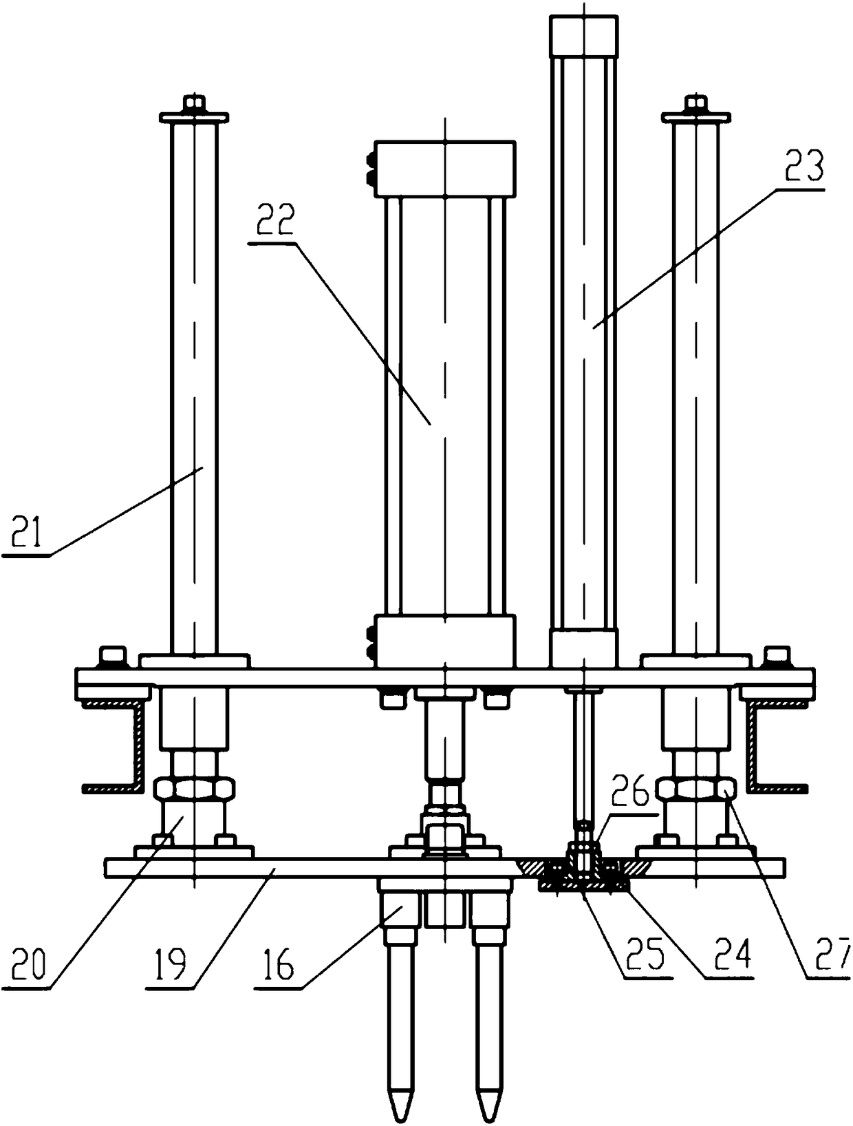
[0031] Please refer to Figure 1-Figure 3 , figure 1 Schematic diagram of the structure of the ceramic fiber integral module punching machine provided by the embodiment of the present invention; figure 2 Schematic diagram of the structure of the punching device provided by the embodiment of the present invention; image 3 It is a schemati...


PUM


Abstract

The invention discloses a punching machine for an integral ceramic fiber module. During use, the to-be-punched integral ceramic fiber module is placed on a workbench, then a second air cylinder pushesan anti-rising plate to move downwards until the anti-rising plate just makes contact with the integral ceramic fiber module, then a first air cylinder pushes pressing heads to move downwards in thevertical direction to perform punching, when the pressing heads return, the anti-rising plate still blocks the integral ceramic fiber module so as to make the integral ceramic fiber module stay on theworkbench, when the pressing heads are completely separated from the integral ceramic fiber module, the anti-rising plate returns to the original position in the vertical direction under the action of the second air cylinder, so that one punching cycle is completed; and the above operation steps of punching are repeatedly executed, and therefore continuous punching can be carried out on the integral ceramic fiber module, the punching efficiency of the integral ceramic fiber module is improved, and the influence of human factors on the product quality is eliminated.

Description

technical field [0001] The invention relates to the technical field of ceramic fiber equipment, in particular to a ceramic fiber integral module punching machine. Background technique [0002] The ceramic fiber overall module is composed of an integrated fiber blanket and a special metal skeleton interspersed in the middle; it has the advantages of quick assembly and simple construction and installation. heat-resistant lining products. [0003] Before installing the metal frame, it is necessary to drill holes in the overall fiber blanket. At present, the punching of integral fiber blankets is mainly done manually. This process method not only has low production efficiency, but also is not easy to control the product quality; it often causes quality problems such as uneven punching depth and punching inclination. In the case of rising human resource costs and fierce market competition, improving production efficiency and product quality is an important means to ensure that...

Claims


Application Information

Patent Timeline
Patent Type & Authority Applications(China)
IPC IPC(8): B26F1/14B26D5/12B26D7/01
CPCB26D5/12B26D7/01B26F1/14
Inventor 褚万顺陈晓波赵生祥岳耀辉荆桂花
Owner LUYANG ENERGY SAVING MATERIALS CO LTD
Why Eureka
Try Eureka