Rail carrier

A carrier and rail technology, applied in transportation and packaging, conveyors, mechanical conveyors, etc., can solve the problems of waiting for robots, time-consuming model switching, and inability to meet the needs of automobile factories, and achieve safe and reliable operation, convenient operation, and convenient efficiency. Effect

Inactive Publication Date: 2018-06-01
新昌县双彩乡捷丰五金厂
0 Cites 0 Cited by

AI-Extracted Technical Summary

Problems solved by technology

At present, most domestic technologies are limited to special equipment for a single model to realize this function. This equipment is time-consuming for model switching and is not suitable for flexibl...

Abstract

The invention relates to a rail carrier. The rail carrier comprises a rail frame with a first rail and a second rail, a lifting bracket mechanism, a rail motor and a rail gear, wherein the lifting bracket mechanism is mounted on the first rail; the lifting bracket mechanism is mounted on the second rail; a rail rack is engaged with the rail gear; the rail motor is connected with the rail gear andis mounted on the lifting bracket mechanism; the rail motor drives the rail gear to rotate, so that the lifting bracket mechanism moves; the lifting bracket mechanism comprises a lifting mechanism, aworkpiece front side bracket mechanism and a workpiece rear side bracket mechanism; the workpiece rear side bracket mechanism comprises a clamping arm, a supporting block, a swing air cylinder and a travelling mechanism; the workpiece front side bracket mechanism comprises a clamping arm, a supporting block and a swing air cylinder; and positioning grooves which are formed at intervals and are suitable for different widths of workpieces are formed in the supporting surface of the supporting block. The rail carrier is suitable for carrying workpieces of different vehicle models, is convenient to position and regulate, is high in regulating efficiency, and enables welding quality to be stable.

Application Domain

Technology Topic

Image

  • Rail carrier
  • Rail carrier
  • Rail carrier

Examples

  • Experimental program(1)

Example Embodiment

[0030] The present invention will be further described below:
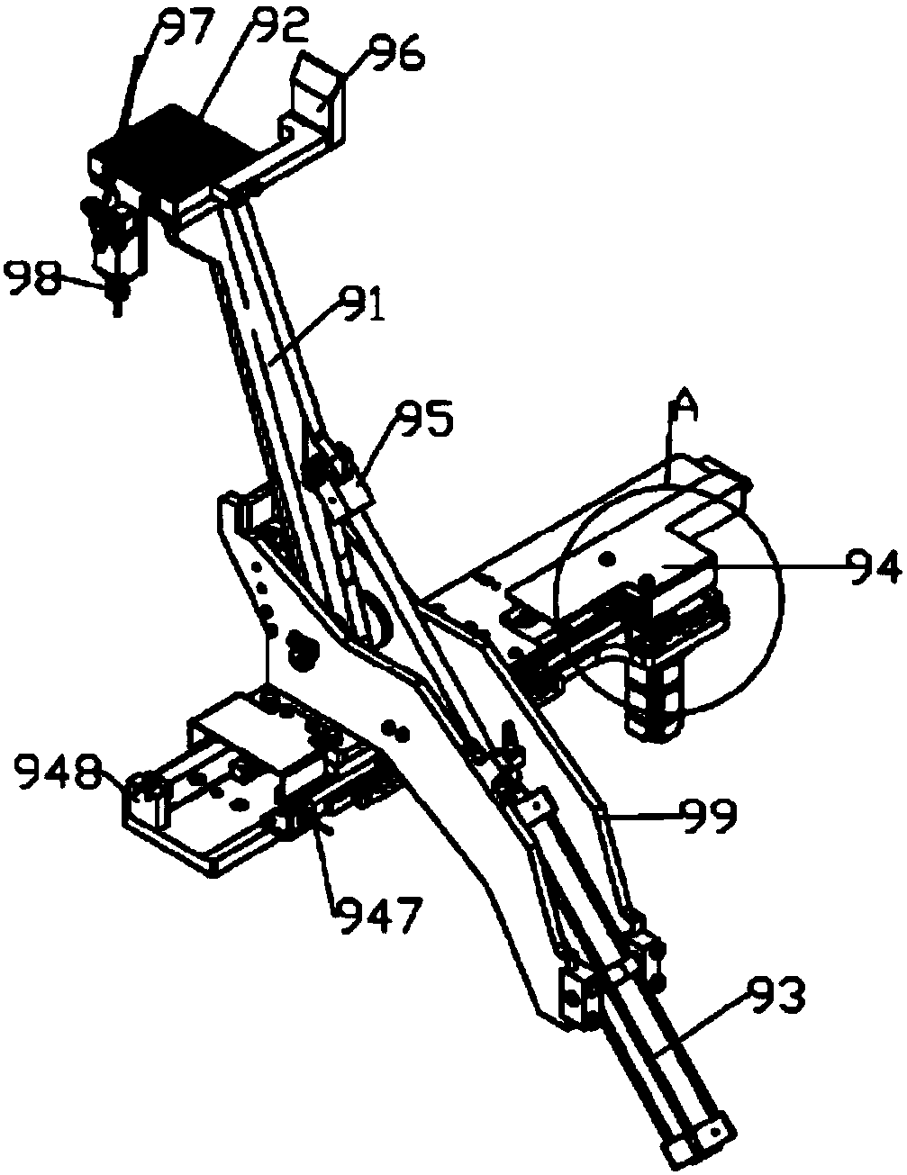
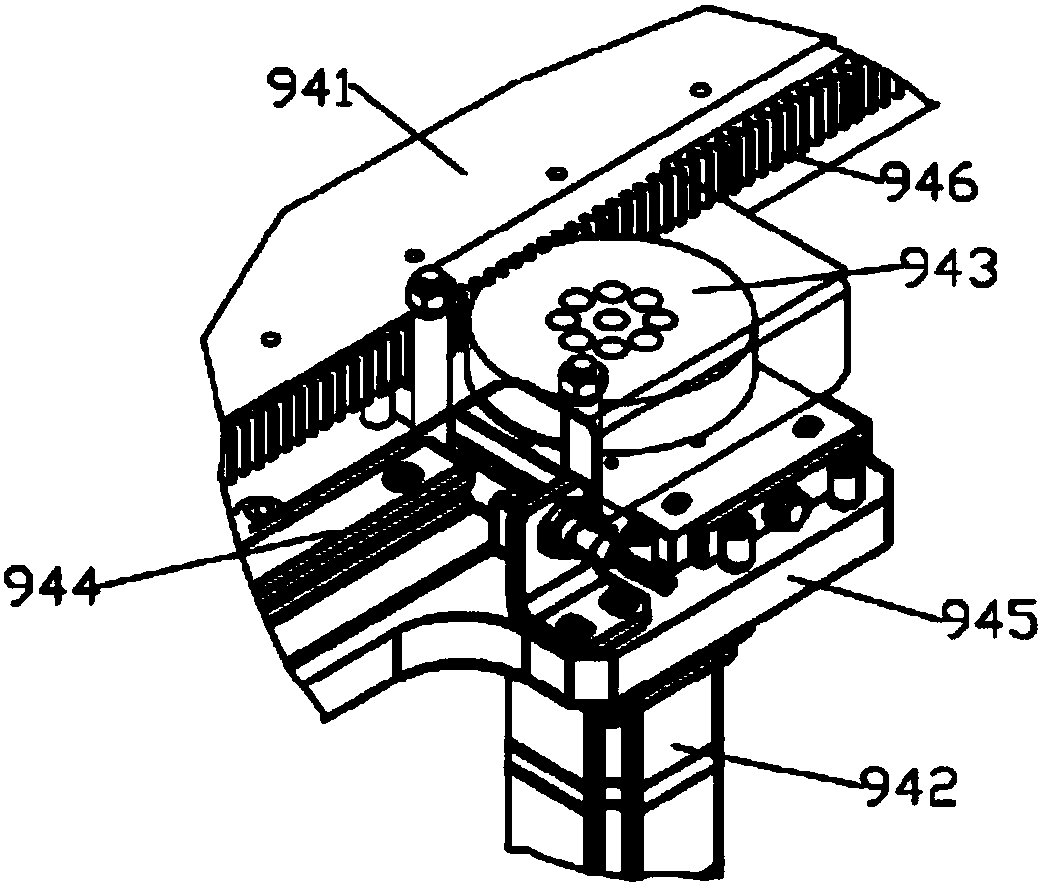
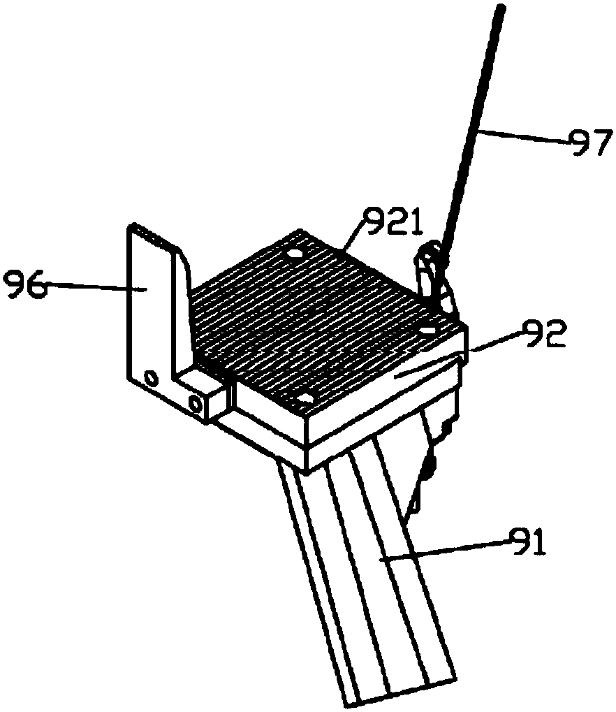
[0031] Figure 1-Figure 8 The following components are shown in the diagram: the first track 1, the second track 2, the track frame 3, the track motor 4, the track gear 5, the guide rail 6, the track rack 7, the slider 61, the lifting mechanism 8, the bracket mechanism 9. Workpiece front side bracket mechanism 10, workpiece rear side bracket mechanism 11, first bracket mechanism 101, second bracket mechanism 102, third bracket mechanism 111, fourth bracket mechanism 112, clamping arm 91 , Support block 92, swing cylinder 93, walking mechanism 94, cylinder connector 95, guide block 96, limit rod 97, limit switch 98, angle iron 99, lifting fixed platform 81, lifting movable platform 82, lifting Lifting linear guide 83, lifting rack 84, lifting gear 85, lifting motor 86, lifting displacement overtravel protection device 87, locking cylinder 88 of the platform, mounting platform 821 of the rear bracket mechanism of the workpiece, front of the workpiece The mounting platform 822 of the side bracket mechanism, the upper jack 89 and the lower jack 810 fixed on the lifting movable platform, the scale 811, the sawtooth positioning groove 921, the fixed plate 941, the traveling servo motor 942, the traveling The gear 943, the walking linear guide 944, the mounting plate 945, the traveling rack 946, the overtravel detection mechanism 947 of the traveling mechanism, and the limit block 948 that limits the carriage mechanism.
[0032] Such as Figure 8 , A rail carrier of the present invention, that is, a transport device for body assemblies and/or body floor assemblies of different models, includes a rail frame 3 provided with a first rail 1 and a second rail 2, a lifting bracket mechanism, The track motor 4 and the track gear 5, the first track and the second track are both provided with a guide rail 6 and a track rack 7, the lifting bracket mechanism is provided with a sliding block 61 matched with the guide rail, and the first track is equipped with a lifting Lifting bracket mechanism, a lifting bracket mechanism is installed on the second track, the rail rack 7 meshes with the track gear 5, the track motor 4 is connected with the track gear 5 and is installed on the lifting bracket mechanism, and the track motor 4 drives the track The gear 5 rotates to move the lifting bracket mechanism. The lifting bracket mechanism includes a lifting mechanism 8, a workpiece front bracket mechanism 10, and a workpiece rear bracket mechanism 11. The aforementioned workpieces refer to the body assembly and/or body floor assembly of different models. The design and adjustment of various parts in the handling equipment can be suitable for different workpieces, such as the body assembly of different models, or Is the body floor assembly, or the body assembly and the body floor assembly are common.
[0033] Such as Figure 7 The structure of the bracket device is illustrated, which is composed of a workpiece front side bracket mechanism 10 and a workpiece rear side bracket mechanism 11. The workpiece front side bracket mechanism 10 is composed of a first bracket mechanism 101 and a second bracket mechanism 102, and the two bracket mechanisms are arranged opposite to each other. The workpiece rear side bracket mechanism 11 is composed of a third bracket mechanism 111 and a fourth bracket mechanism. The mechanism 112 is composed of two bracket mechanisms opposite to each other. The first bracket mechanism 101 is fixed to the side of the lifting bracket mechanism of the first rail, and the third bracket mechanism 111 is fixed to the lifting bracket of the first rail. On the other side of the mechanism, the second bracket mechanism 102 is fixed on one side of the lifting bracket mechanism of the second track, and the fourth bracket mechanism 112 is fixed on the other side of the lifting bracket mechanism of the second track. By the way, the third bracket mechanism and the fourth bracket mechanism are both bracket mechanisms 9 of the same structure, such as figure 1 , figure 2 , Each includes a clamping arm 91, a support block 92, a swing cylinder 93 and a traveling mechanism 94. The support block 92 is fixed on the top end of the clamping arm 91, the bottom of the clamping arm 91 is hinged on the traveling mechanism 94, and the swing cylinder 93 is fixed. On the traveling mechanism, the piston rod of the swing cylinder 93 is hinged with the clamping arm 91 through the cylinder connector 95. The traveling mechanism 94 drives the clamping arm and the swing cylinder to move together, and the swing cylinder 93 pushes the clamping arm to swing; the first bracket The mechanism and the second bracket mechanism both include a clamping arm, a support block and a swing cylinder. The support block is also fixed at the top of the clamping arm. The piston rod of the swing cylinder is hinged with the clamping arm through the cylinder connector, and the swing cylinder pushes The clamping arm swings, wherein the bottom of the clamping arm is hinged on the lifting bracket mechanism and the swing cylinder is fixed on the lifting bracket mechanism, and the two do not move with the walking mechanism. It can be seen that the first bracket mechanism and the second bracket The difference between the bracket mechanism and the third bracket mechanism and the fourth bracket mechanism is that the first bracket mechanism and the second bracket mechanism are not provided with a running mechanism. The clamping arm 91 and the swing cylinder 93 in the bracket mechanism 9 are mounted on the walking mechanism through an angle iron 99. The angle iron 99 is a long strip with a head and a tail, and is connected by two parallel spaced side surfaces. The bottom surface of the two side surfaces is composed of a mounting plane on the angle iron 99 near the head end and an iron block is fixed on the mounting plane. A shaft hole is provided on the angle iron 99 and above the mounting plane, and a clamping arm 91 is installed through a rotating shaft and a rotating shaft hole on the angle iron, and the cylinder body of the swing cylinder 93 is fixed at the tail of the angle iron 99. The clamping arm is also provided with a structure, that is, the clamping arm on the bracket mechanism on the rail on one side of the rail frame is provided with two ends and two arm sections. The two arm sections are connected to form a "V "Shaped structure, the cylinder connector is set in the middle of one of the arm sections, and the connecting part of the two arm sections is set with a hinge position, so that the rail frame can be arranged side by side, and the bracket mechanism on one rail on the other rail frame Form a combination.
[0034] Such as figure 2 The walking mechanism 94 includes a fixed plate 941, a walking servo motor 942, a walking gear 943, a walking linear guide 944, and a mounting plate 945. The walking linear guide 944 is installed between the fixed plate and the mounting plate, and the walking servo motor and the walking gear are installed in the installation At one end of the board, the traveling servo motor is connected with the traveling gear. The fixed board is provided with a board top surface, a board bottom surface, two end surfaces and side sides on both sides. The top surface of one end of the fixed board is equipped with a bracket based on multi-model handling equipment In the installation position of the mechanism, one side of the other end of the fixed plate is installed with a traveling rack 946 that meshes with the traveling gear. The traveling servo motor drives the traveling gear to rotate, and the fixed plate moves on the mounting plate through the traveling linear guide. An overtravel detection mechanism 947 of the walking mechanism is provided on the sides of both ends of the walking linear guide rail. The overtravel detection mechanism includes a proximity switch and its signal output line system. A speed reduction mechanism is provided between the traveling servo motor and the traveling gear assembly, and a limit block 948 for limiting the position of the carrier mechanism is provided on the mounting plate and near the end of the mounting position of the carrier mechanism based on multi-model handling equipment .
[0035] Such as image 3 The support surface of the support block 92 is provided with spaced positioning grooves for adapting to different widths of the workpiece, such as formed into a sawtooth positioning groove 921, the support block 92 and the sawtooth positioning groove on the support block 92 are also called sawtooth support Piece. A guide block 96 for workpiece placement is provided on one side of the support block 92, and a limit rod 97 is provided on the other side of the support block. The guide block 96 and the limit rod 97 are disposed opposite to each other. A limit switch 98 is provided at the position of the limit rod 97. The guide block 96 is composed of a vertical block perpendicular to the supporting surface of the supporting block and a connecting block connected to the supporting block. The top end of the vertical block is provided with a guiding inclined surface. The limit rod 97 is fixed on the support block by an adjusting structure, and the limit switch 98 is triggered by the limit rod 97 to act. The positioning groove is also called a positioning groove, meaning a groove used for positioning.
[0036] Such as Figure 4 , Figure 5 , Image 6 , The lifting mechanism 8 includes a lifting fixed platform 81, a lifting movable platform 82, a driving device, and a vertical lifting linear guide 83. The lifting movable platform 82 is installed on the lifting fixed platform 81 through the lifting linear guide. , The driving device is connected with the lifting movable platform 82, the lifting movable platform 82 is driven by the driving device to move vertically on the lifting fixed platform through the lifting linear guide rail, and the lifting fixed platform 81 is provided with a lifting The locking mechanism after the movable platform is lifted. The driving device includes a lifting rack 84, a lifting gear 85, and a lifting motor 86. The lifting motor is connected to the lifting gear and fixed on the lifting fixed platform, and the lifting rack is vertically fixed on the lifting movable platform. The lifting fixed platform 81 is welded by four frames. The connecting rods arranged vertically and horizontally are welded in the box surrounded by the four frames. The lifting linear guide rail is installed on the vertical frame on one side, such as the guide rail. The sides of both ends of the lifting linear guide rail are provided with a lifting displacement overtravel protection device 87. The lifting displacement overtravel protection device includes a proximity switch and a data line system connected to the proximity switch. The lifting movable platform 82 includes a four-frame body welded by four frames. A tripod is provided on both sides of the vertical frame of the four-frame body, and one side of the tripod is horizontal. A strip-shaped carrying platform is fixed on the horizontal side of the tripod to constitute the installation platform 821 of the rear bracket mechanism of the workpiece, and the horizontal side of the tripod on the other side is fixed with a square carrying platform to constitute the installation platform 822 of the front bracket mechanism of the workpiece. The vertical frame on one side of the four frame body of the lifting movable platform is also equipped with a lifting linear guide member such as a slider. The locking mechanism includes a locking cylinder 88 for lifting the movable platform, an upper insertion hole 89 and a lower insertion hole 810 fixed on the lifting movable platform, and the piston of the locking cylinder is inserted into the upper or lower insertion hole. Lock the lifting movable platform in the jack of. A scale 811 is also provided on the vertical side of the lifting fixed platform.

PUM

no PUM

Description & Claims & Application Information

We can also present the details of the Description, Claims and Application information to help users get a comprehensive understanding of the technical details of the patent, such as background art, summary of invention, brief description of drawings, description of embodiments, and other original content. On the other hand, users can also determine the specific scope of protection of the technology through the list of claims; as well as understand the changes in the life cycle of the technology with the presentation of the patent timeline. Login to view more.

Similar technology patents

Classification and recommendation of technical efficacy words

  • Convenience and efficiency
  • Easy to operate

Airing equipment for linen and cotton primary processing

InactiveCN107560365AGood air drying effectConvenience and efficiencyDrying gas arrangementsDrying machines with non-progressive movementsEngineeringAir drying
Owner:南京极佳物联网科技有限公司

Coal mine underground positioning dust removal system

PendingCN112554949AIntelligent operationConvenience and efficiencyMining devicesDust removalCoalMining engineering
Owner:TAIYUAN UNIV OF TECH
Why Eureka
Try Eureka