Electroplating groove

A technology of electroplating tank and tank body, applied in the direction of plating tank, electrolysis process, electrolysis components, etc., can solve problems such as easy overflow and temperature difference of electroplating solution, and achieve the effect of avoiding temperature difference

Pending Publication Date: 2018-06-01
遵义市汇川区吉美电镀有限责任公司
View PDF9 Cites 6 Cited by
  • Summary
  • Abstract
  • Description
  • Claims
  • Application Information

AI Technical Summary

Problems solved by technology

[0005] The present invention intends to provide an electroplating tank to solve the problem that the electroplating solution in the prior art electroplating tank has temperature difference and is easy to overflow

Method used


Image

  • Electroplating groove

Examples


Embodiment 1

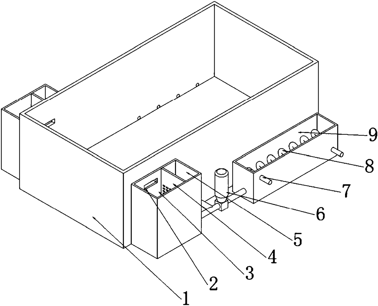
[0017] Example 1 as figure 1 Shown: the electroplating tank of the present invention comprises a main tank body 1 and two sets of overflow tanks and temperature-variable tanks 9 that are matched with each other. A temperature-variable pump 6 is arranged between the overflow tank and the temperature-variable tank 9. The overflow tank and the temperature-variable tank 9 are It is connected with the variable temperature pump 6 through pipelines, wherein an overflow port 2 is provided on the outer walls of the two sides of the main tank body, and the overflow port 2 is connected to the overflow tank, and the overflow tank is composed of the settling chamber 3 and the clear liquid The settling chamber 3 and the clear liquid chamber 5 are separated by a filter screen 4. This filter screen 4 is used to isolate impurities and sediments. In order to ensure the settling effect and filtering effect, the inner bottom of the settling chamber 3 is low. On the inner bottom surface of the cle...


PUM


Abstract

The invention discloses an electroplating groove including a main groove body, an overflow groove, a varying temperature groove and a varying temperature pump. An overflow outlet is formed in the outer wall of the main groove body, the overflow outlet is in communication with the overflow groove, and the varying temperature groove includes an inlet, an outlet and a varying temperature pipe. The overflow groove and the main groove are both in communication with a liquid inlet of the varying temperature pump, and a liquid outlet of the varying temperature pump is in communication with the inlet.The varying temperature pipe is arranged in the varying temperature groove, the outlet is in communication with the main groove body, and the inlet and the outlet of the varying temperature pipe arecorrespondingly in communication with a varying temperature liquid pipe. The liquid is prevented from splashing out by arranging the overflow outlet and the overflow groove. In order to avoid the temperature difference between the electroplating liquid due to the deep groove, the varying temperature groove is arranged. The electroplating liquid in the overflow groove and the main groove body is sent into the varying temperature groove for heat exchange by the varying temperature pump, so that firstly, the temperature of the electroplating liquid can be adjusted, and secondly it is ensured thatthe temperature of the electroplating liquid in the main groove body is all equal through continuous circulation so as to avoid the temperature difference.

Description

technical field [0001] The invention belongs to the technical field of electroplating, and in particular relates to an electroplating tank. Background technique [0002] Electroplating is the process of plating a thin layer of other metals or alloys on the surface of certain metals using the principle of electrolysis. It is a process of using electrolysis to attach a layer of metal film to the surface of metal or other material parts to prevent metal oxidation ( Such as rust), improve wear resistance, electrical conductivity, reflective properties, corrosion resistance (copper sulfate, etc.) and enhance the appearance. [0003] The electroplating tank is the most basic supporting facility in the electroplating equipment. The general electroplating tank is a vertical electroplating tank. The electroplating tank is a cylindrical or square electroplating tank. When electroplating, the components to be electroplated are placed in the electroplating tank. It can be picked up aft...

Claims


Application Information

Patent Timeline
Patent Type & Authority Applications(China)
IPC IPC(8): C25D17/02C25D21/02C25D21/06C25D17/06
CPCC25D17/02C25D17/06C25D21/02C25D21/06
Inventor 朱健瑜王汉张奎
Owner 遵义市汇川区吉美电镀有限责任公司
Why Eureka
Try Eureka