
A multi-beamforming network lens structure with high transmission coefficient

A technology of forming network and lens structure, applied in the direction of antenna, electrical components, etc., can solve the problems of suppressing return loss and high return loss, and achieve the effect of reducing return loss, increasing transmittance and high transmittance coefficient

Active Publication Date: 2020-12-29
CHENGDU AERONAUTIC POLYTECHNIC
View PDF8 Cites 0 Cited by
  • Summary
  • Abstract
  • Description
  • Claims
  • Application Information

AI Technical Summary

Problems solved by technology

Due to the different paths from the beam port to the array port, the return loss cannot be suppressed by propagation paths that are integer multiples of a quarter wavelength
However, the small impedance mismatch of the tapered line in engineering cannot be avoided, so the high return loss is one of the main defects of the beamforming network

Method used


Image

  • A multi-beamforming network lens structure with high transmission coefficient
  • A multi-beamforming network lens structure with high transmission coefficient
  • A multi-beamforming network lens structure with high transmission coefficient

Examples


Embodiment Construction

[0026] The invention provides a multi-beam forming network lens structure with high transmittance coefficient, which can reduce the return loss of this type of device and increase the transmittance of the lens.

[0027] In order to understand the above-mentioned purpose, features and advantages of the present invention more clearly, the present invention will be further described in detail below in conjunction with the accompanying drawings and specific embodiments. It should be noted that, under the condition of not conflicting with each other, the embodiments of the present application and the features in the embodiments can be combined with each other.

[0028] In the following description, many specific details are set forth in order to fully understand the present invention. However, the present invention can also be implemented in other ways different from the scope of this description. Therefore, the protection scope of the present invention is not limited by the followi...


PUM


Abstract

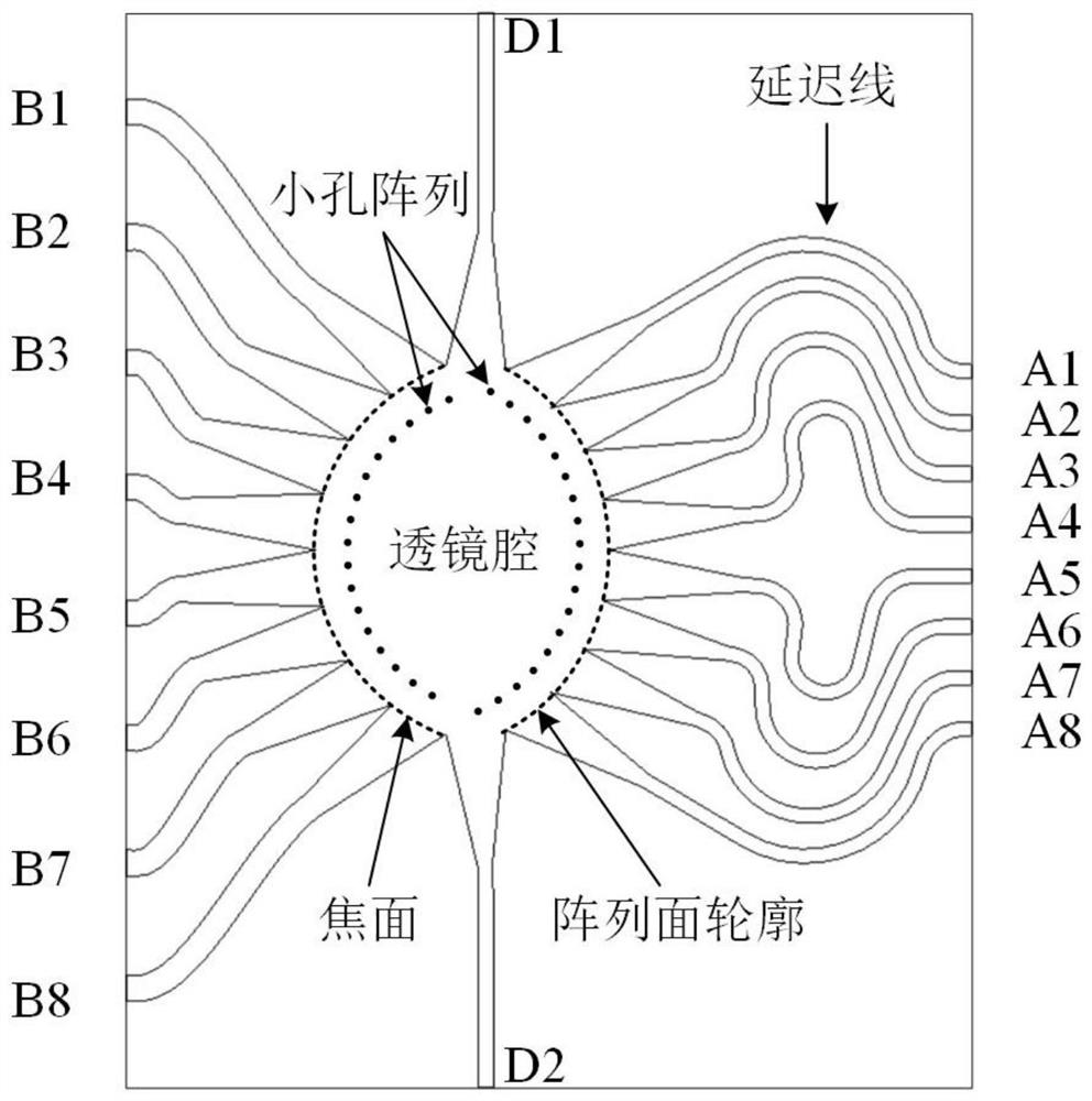
The invention discloses a multi-beam forming network lens structure having high transmittance coefficient. The structure comprises a lens which is provided with multiple beam ports. The beam ports areled into a lens cavity through a feeder line. The other end of the lens cavity is connected with multiple array ports through a phase delay feeder line. At least one row of hole array is arranged onthe position, which is parallel to the focal plane and array plane profile, in the lens cavity. The echo loss of the device can be reduced and the transmittance of the lens can be increased.

Description

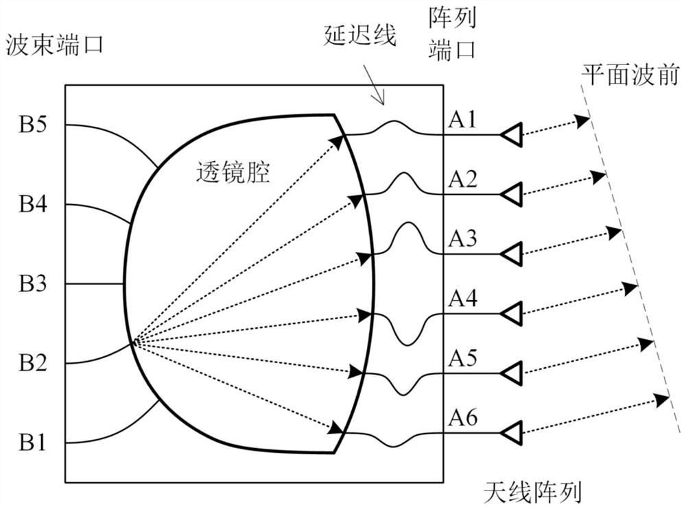
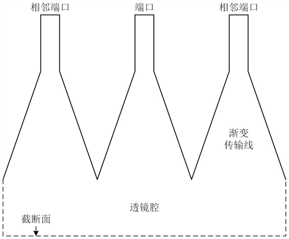
technical field [0001] The invention relates to the field of multi-beam forming network lenses, in particular to a multi-beam forming network lens structure with high transmission coefficient. Background technique [0002] The beamforming network device is a kind of passive microwave network device with multiple input and multiple output ports, and its specific forms include Rotman lens, Bootlace lens and so on. The general structure of a beamforming network is as figure 1 As shown, multiple beam ports (Beam Ports) are introduced into the lens cavity (Lens Cavity) through feeders, and the other end of the lens cavity is connected to multiple array ports (Array Ports) through a specially calculated phase delay feeder line, and antennas are connected to the array ports to form a antenna array. The feeder is connected to the lens cavity through a tapered transmission line structure to achieve impedance matching. The tapered transmission line structure is as figure 2 shown. ...

Claims


Application Information

Patent Timeline
Patent Type & Authority Patents(China)
IPC IPC(8): H01Q15/10
CPCH01Q15/10
Inventor 邓建华漆静吕欣
Owner CHENGDU AERONAUTIC POLYTECHNIC
Learn More