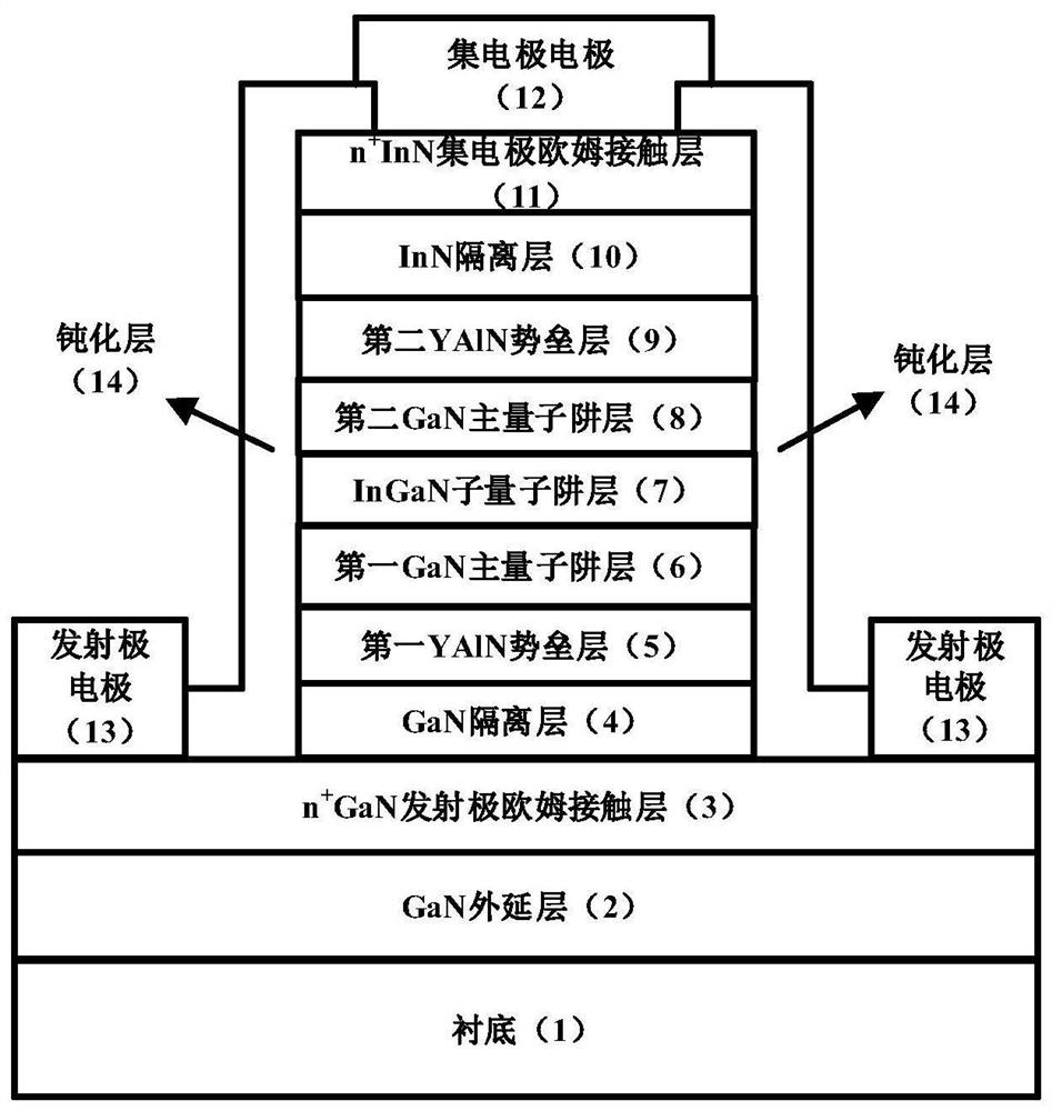
YAlN/GaN double-barrier resonant tunneling diode containing InGaN sub-well structure and manufacturing method of YAlN/GaN double-barrier resonant tunneling diode
A resonant tunneling and double barrier technology, which is applied in the direction of diodes, semiconductor/solid-state device manufacturing, electrical components, etc., can solve the problem of increased peak voltage and power consumption of devices, uneven distribution of dislocations in active regions of devices, and ohmic contact of collectors. The problem of high resistance can reduce the peak voltage and power consumption of the device, realize the differential negative resistance effect of symmetrical characteristics, and reduce the width of the depletion region.
- Summary
- Abstract
- Description
- Claims
- Application Information
AI Technical Summary
Problems solved by technology
Method used
Image
Examples
Embodiment 1
[0063] Embodiment 1, on a self-supporting gallium nitride substrate, Y 0.11 Al 0.89 N barrier layer, In 0.04 Ga 0.96 YAlN / GaN double potential barrier resonant tunneling diode with N sub-quantum well layer.
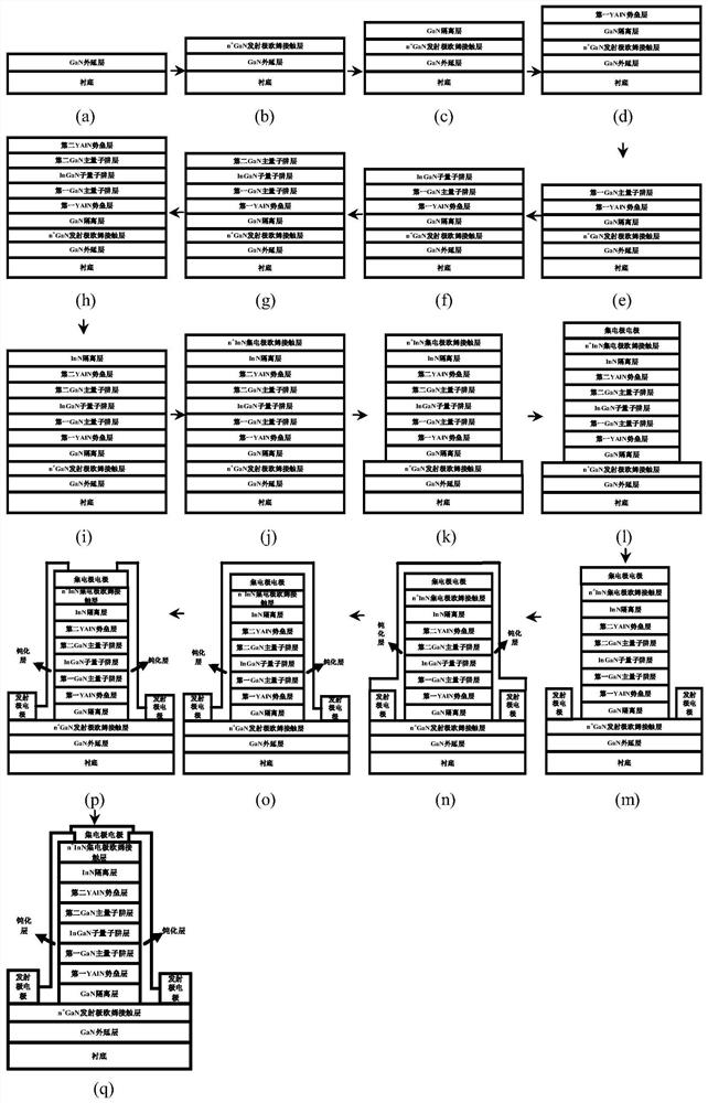
[0064] Step 1, growing a GaN epitaxial layer, such as image 3 (a).
[0065] A GaN epitaxial layer with a thickness of 1500nm is grown on a self-supporting gallium nitride substrate by molecular beam epitaxy.
[0066] The process conditions used to grow the GaN epitaxial layer are: the temperature is 700°C, the equilibrium vapor pressure of the gallium beam is 8.0×10 - 7 Torr, the flow rate of nitrogen gas is 2.3sccm, and the power of the nitrogen plasma RF source is 375W.
[0067] Step two, grow n + GaN emitter ohmic contact layer, such as image 3 (b).
[0068] Using the molecular beam epitaxy method, the thickness of the GaN epitaxial layer is 100nm, and the doping concentration is 1x10 20 cm -3 the n + GaN emitter ohmic contact layer.
[0069] grow n + ...
Embodiment 2
[0145] Embodiment two, on the sapphire substrate, make and adopt Y 0.15 Al 0.85 N barrier layer and In 0.05 Ga 0.95 YAlN / GaN double barrier resonant tunneling diode of N sub quantum well.
[0146] Step 1, grow GaN epitaxial layer, such as image 3 (a).
[0147] Using the metal-organic chemical vapor deposition method, using the process conditions of temperature 1050°C, pressure 40Torr, ammonia flow rate 2000sccm, gallium source flow rate 120sccm, hydrogen flow rate 3000sccm, on a sapphire substrate, a thickness of 3000nm was grown. GaN epitaxial layer.
[0148] Step 2, grow n + GaN emitter ohmic contact layer, such as image 3 (b).
[0149] Using the molecular beam epitaxy method, the temperature is 720°C, and the equilibrium vapor pressure of the gallium beam is 8.5×10 -7 Torr, silicon beam equilibrium vapor pressure is 3.2×10 -8 Torr, the nitrogen flow rate is 2.3sccm, the nitrogen plasma RF source power is 375W, the thickness of the GaN epitaxial layer is 200nm, a...
Embodiment 3
[0192] Embodiment 3, on the silicon substrate, manufacture adopts Y 0.06 al 0.94 N barrier layer and and In 0.03 Ga 0.97 YAlN / GaN double potential barrier resonant tunneling diode with N sub-quantum well layer.
[0193] Step A, growing a GaN epitaxial layer, such as image 3 (a).
[0194] Set the temperature at 1100°C, the pressure at 40 Torr, the flow rate of ammonia gas at 2000 sccm, the flow rate of gallium source at 100 sccm, and the flow rate of hydrogen gas at 3000 sccm, and use the metal-organic chemical vapor deposition method to grow a GaN epitaxial layer with a thickness of 4000 nm on the Si substrate. .
[0195] Step B, grow n + GaN emitter ohmic contact layer, such as image 3 (b).
[0196] Set the temperature to 680°C, and the equilibrium vapor pressure of the gallium beam to 7.5×10 -7 Torr, silicon beam equilibrium vapor pressure is 3.0×10 -8 Torr, the flow rate of nitrogen gas is 2.3sccm, the power of the nitrogen plasma RF source is 375W, and the m...
PUM
| Property | Measurement | Unit |
|---|---|---|
| thickness | aaaaa | aaaaa |
| thickness | aaaaa | aaaaa |
| thickness | aaaaa | aaaaa |
Abstract
Description
Claims
Application Information
 - R&D
- Intellectual Property
- Life Sciences
- Materials
- Tech Scout
- Unparalleled Data Quality
- Higher Quality Content
- 60% Fewer Hallucinations
Browse by: Latest US Patents, China's latest patents, Technical Efficacy Thesaurus, Application Domain, Technology Topic, Popular Technical Reports.
© 2025 PatSnap. All rights reserved.Legal|Privacy policy|Modern Slavery Act Transparency Statement|Sitemap|About US| Contact US: help@patsnap.com


