Light emiting diodes with current spreading layer

a technology of light-emitting diodes and current spreading layers, which is applied in the direction of basic electric elements, electrical equipment, semiconductor devices, etc., can solve the problems of increasing manufacturing costs, not being suitable for growing algainp crystal layers, and not being suitable for thick window layers for some device configurations

Active Publication Date: 2005-02-17
DICON FIBEROPTICS
View PDF7 Cites 128 Cited by
  • Summary
  • Abstract
  • Description
  • Claims
  • Application Information

AI Technical Summary

Benefits of technology

[0008] According to an additional embodiment of the invention, a light emitting diode comprises an active light emission layer and a semiconductor layer over the active layer which pases light emitted by the active layer as light output from the diode. A current spreading composite layer is employed on the semiconductor layer. The composite layer includes a first metallic layer of not more than about 8 nm in total thickness in contact with said semiconductor layer, and a second current spreading layer in contact with said first metallic layer. The two layers in the current spreading composite layer are substantially transparent to light emitted by the active layer.
[0009] Another embodiment of the i...

Problems solved by technology

The conventional growth techniques such as liquid phase epitaxy (LPE) and hydride vapor phase epitaxy (HVPE) were not suitable for growing AlGaInP crystal layer.
But, its drawback is the extremely high thickness, which results in increasing manufacturing cost.
The thick window layer is also not suitable for some device configurations—such as resonant cavi...

Method used


Image

  • Light emiting diodes with current spreading layer
  • Light emiting diodes with current spreading layer
  • Light emiting diodes with current spreading layer

Examples


first embodiment

[0027] In the present invention, a light emitting diode comprises an ultra-thin composite metallic layer between the transparent current spreading layer and p-type semiconductor layer to form a good ohmic contact without sacrificing the light transparency. The ultra-thin metallic layer comprises at least one type of metal. Typically two metal layers such as a first layer of titanium and a second layer of gold may be deposited to form the ultra-thin composite layer. Here, the titanium layer serves as surface cleaning and adhesive agent when deposited over or on the p-type semiconductor layer. The second transparent current spreading layer is a thick ITO layer or its equivalents. The ultra-thin composite metallic layer will facilitate connection to the ITO layer to form an excellent ohmic contact after Rapid Thermal Annealing (RTA) treatment around 330˜440° C. for 0.5 to 2 minutes, which causes some of the metallic layer to diffuse into the ITO layer. The metal thickness of the ultra-...

second embodiment

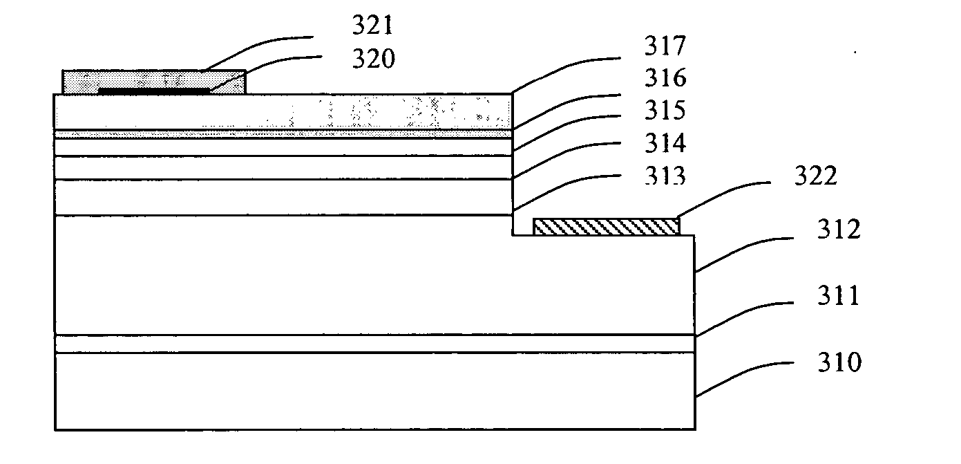
[0033] A second embodiment in the present invention is illustrated schematically in FIG. 7-9 for the LED structure and LED device of GaN-based materials. FIG. 7 shows the top metal (Ni / Au etc.) bonding pad 321 of the LED.

[0034] As illustrated by the structures shown in FIG. 8 and FIG. 9, the LED structure is first grown on the lattice-mismatched insulating sapphire substrate 310 using MOCVD. A very thin low temperature GaN nucleation layer 311 is grown, followed by a thick n-type GaN 312. The active layer 313 comprises several InGaN / GaN strained MQWs. Finally, the p-AlGaN upper cladding layer 314 for electrical confinement and p-GaN contact layer 315 are deposited.

[0035] In the conventional LED structure, the current spreading layer is a thin semi-transparent metal layer such as NiO / Au (transmission is around 60% with thickness of 10 / 30 nm). In the present invention, an ultra-thin composite metallic layer such as Ti / Au, Ti / Au—Zn, Ti / Au—Be, Ti / In—Be or Ni / Au 316, followed by a trans...


PUM


Abstract

A light-emitting diode (LED) for both AlGaInP- and GaN-based materials needs a good transparent current spreading layer to disseminate electrons or holes from the electrode to the active layer. The present invention utilizes a conductive and transparent ITO (Indium Tin Oxide) thin film with an ultra-thin (to minimize the absorption) composite metallic layer to serve as a good ohmic contact and current spreading layer. The present invention avoids the Schottky contact due to direct deposition of ITO on the semiconductor. For AlGaInP materials, a thick GaP current spreading layer is omitted by the present invention. For GaN-based LEDs with the present invention, semi-transparent Ni/Au contact layer is avoided. Therefore, the light extraction of LED can be dramatically improved by the present invention. Holes may be etched into the semiconductor cladding layer forming a Photonic Band Gap structure to improve LED light extraction.

Description

FIELD OF THE INVENTION [0001] The invention relates to the structure and fabrication of light emitting diodes. In particular, the invention can improve the light extraction efficiency and increase the light output. BACKGROUND OF THE INVENTION [0002] AlGaInP-based materials grown on lattice-matched GaAs substrates and GaN-based materials grown on sapphire or SiC substrates have led to major advances in high-brightness LEDs. That LED produces high brightness and posses complete visible spectrum to make solid-state lighting possible. The advancement of LED technology is attributed to the developments of advanced epitaxial growth technologies such as molecular beam epitaxy (MBE) and metal-organic chemical vapor deposition (MOCVD). The conventional growth techniques such as liquid phase epitaxy (LPE) and hydride vapor phase epitaxy (HVPE) were not suitable for growing AlGaInP crystal layer. The advanced epitaxial growth technologies enable the formation of high-quality alloy of III-V mat...

Claims


Application Information

Patent Timeline
IPC IPC(8): H01L31/12H01L33/38H01L33/42
CPCH01L33/42H01L33/38
Inventor LIN, HUI-LIDU, QINGHONGLEE, HO-SHANG
Owner DICON FIBEROPTICS
Why Eureka
Try Eureka