Al technical title is built by PatSnap Al team. It summarizes the technical point description of the patent document.
An installation system and power technology, applied in circuits, electrical components, circuit/collector parts, etc., can solve the problems of cumbersome and complicated processes, affecting installation progress, and high labor intensity, ensuring personnel safety, improving work efficiency, The effect of reducing labor intensity
Inactive Publication Date: 2018-06-01
洪娇娇
View PDF0 Cites 9 Cited by
Summary
Abstract
Description
Claims
Application Information
AI Technical Summary
This helps you quickly interpret patents by identifying the three key elements:
Problems solved by technology
Method used
Benefits of technology
Problems solved by technology
[0003] In order to solve the above problems, the present invention provides an electric power installation system, which can solve the need for personnel to manually install the grounding rod with the help of tools in the process of installing the existing grounding rod. The process is cumbersome and complicated. It may not be fixed in time due to hand slippage, which will affect the installation progress. When installing on soft soil, the personnel directly hammer the ground rod into the soil with the help of a h...
Method used
Image
Click on the blue label to locate the original text in one second.
Reading with bidirectional positioning of images and text.
Examples
Embodiment Construction
[0034] In order to make the technical means, creative features, goals and effects achieved by the present invention easy to understand, the present invention will be further described below in conjunction with specific illustrations. It should be noted that, in the case of no conflict, the embodiments in the present application and the features in the embodiments can be combined with each other.
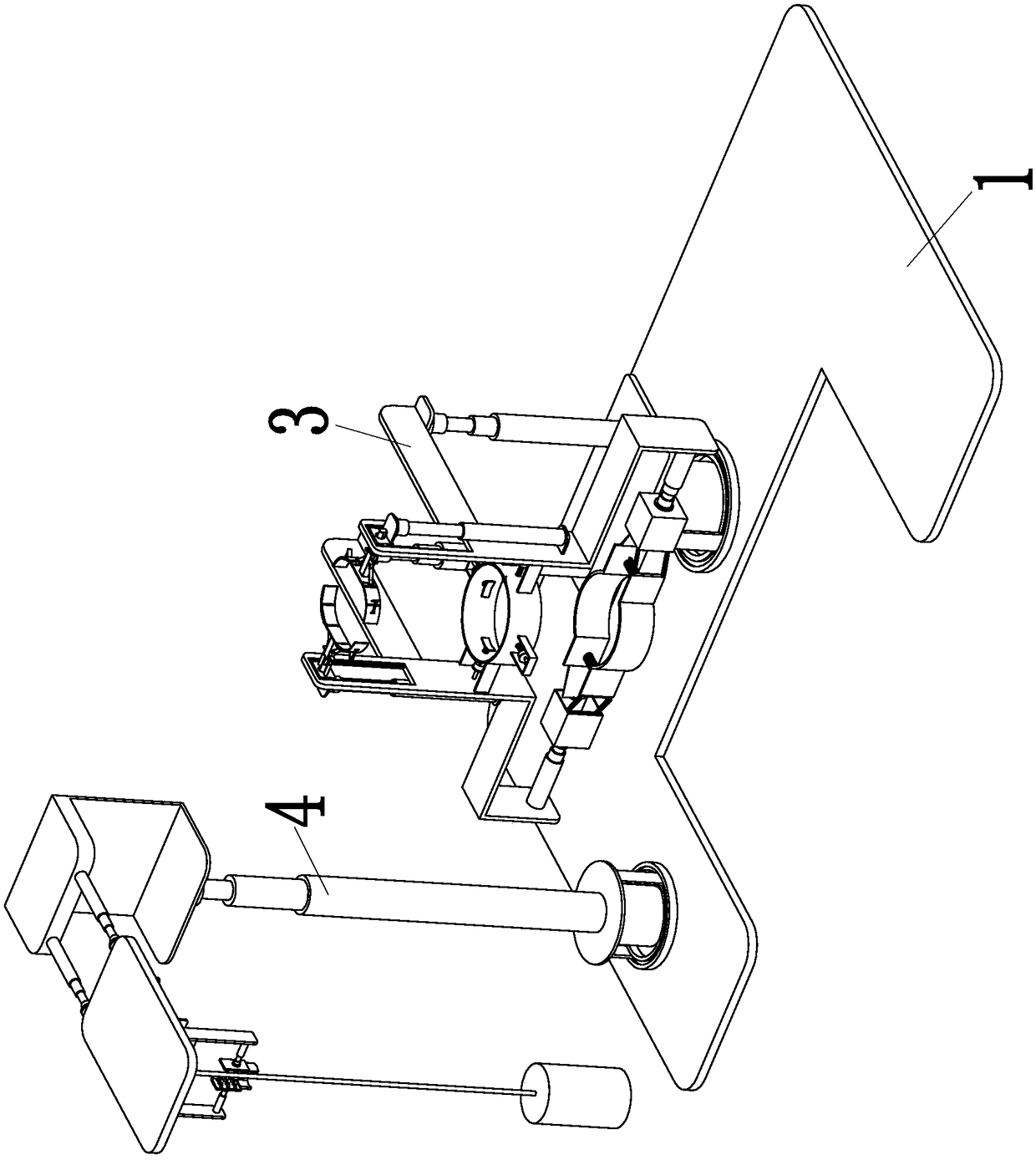
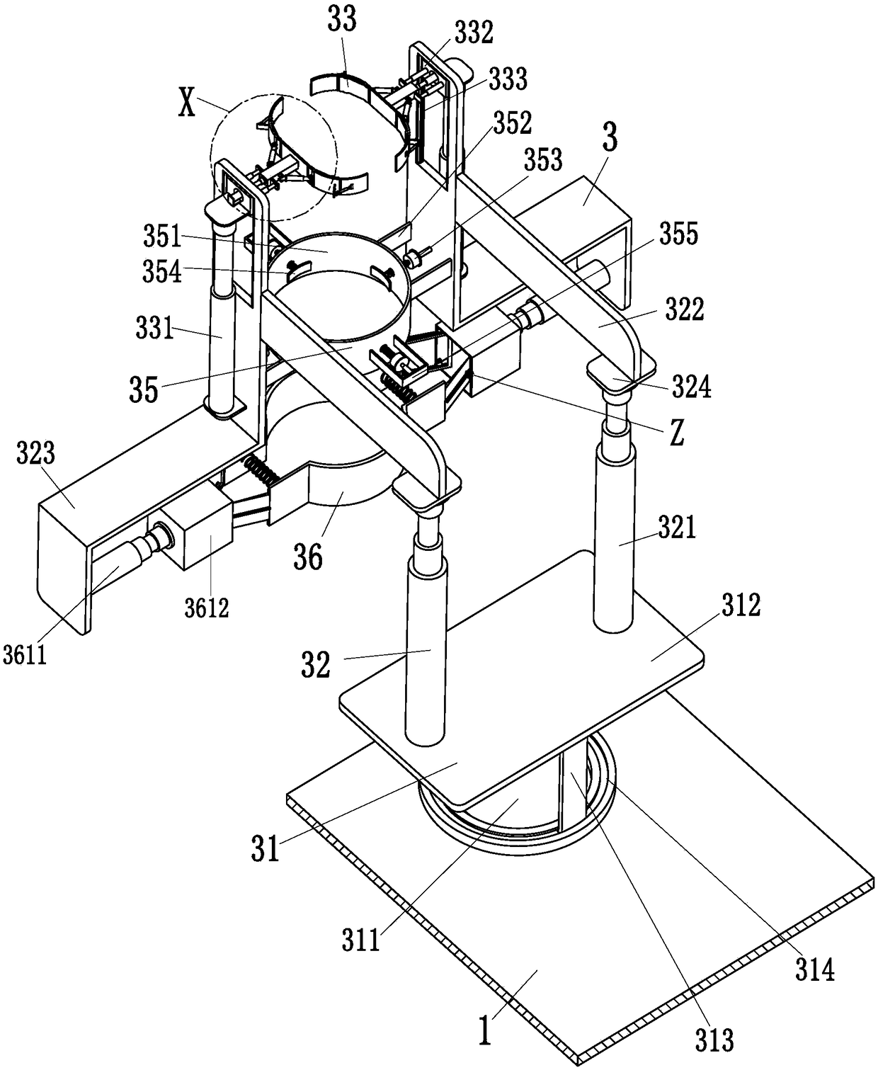
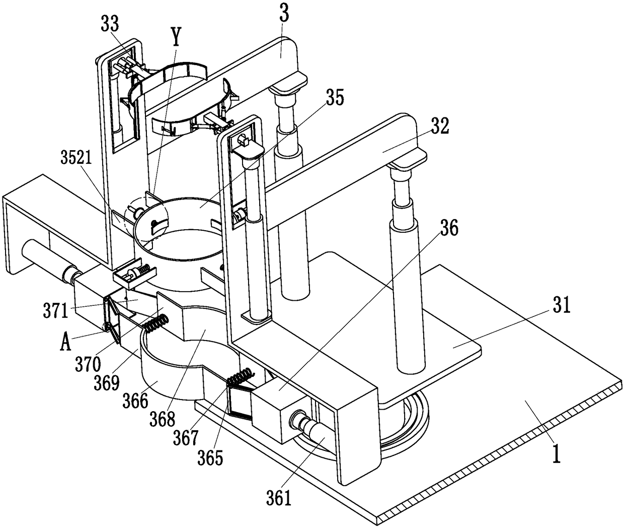
[0035] Such as Figure 1 to Figure 9 As shown, in order to achieve the above object, the present invention adopts the following technical solutions: a power installation system, including a U-shaped main frame 1, a clamping device 3 and a beating device 4, the clamping device 3 clamps the ground rod stably, and the beating device 4. Hammer the ground rod into the soft soil. A clamping device 3 is installed in the middle of the upper end of the U-shaped main frame 1. A beating device 4 is installed on the left side of the upper end of the U-shaped main frame 1. The clamping device 3 a...
PUM
Abstract
The invention relates to an electric power installation system. The electric power installation system comprises a U-shaped main frame, a clamping apparatus and a hamming apparatus, wherein the uppermiddle portion of the U-shaped main frame is provided with the clamping apparatus, and the left side of the upper end of the U-shaped main frame is provided with the hamming apparatus. The electric power installation system can solve the problems that in the processing of installing the existing grounding bar, a tool is needed for manually installing the grounding bar, the process is complicated,the grounding bar needs to be held by people when in installation, the installation progress may be influenced due to the slipping of hand and untimely fixation when in operation, the grounding bar isdirectly hammered into the soil by a hammer when installed in the loose soil, the safety potential hazard may be caused by the hammer hitting the hand due to fault operation, the manual hamming is easy to deviate from the working position, the process time is long, the labor intensity is high, the efficiency is low and the like, and can realize the automatic clamping and installation of the grounding bar in the loose soil.
Description
technical field [0001] The invention relates to the field of electric power, in particular to an electric power installation system. Background technique [0002] Grounding rod, also known as grounding pole, grounding grid, grounding rod is designed and produced on the basis of improving the internal conductivity of the grounding conductor and reducing the external soil resistivity of the grounding conductor. The product has the advantages of simple construction, small footprint, and no environmental pollution. , long service life, economical, excellent electrical conductivity and other characteristics, generally applicable to many fields such as communication, electric power, transportation, finance, petrochemical, building systems, such as communication bureau stations, mobile base stations, dispatching machine rooms, substations, expressway facilities, computers Units and departments that have strict grounding requirements, such as buildings and intelligent communities, c...
Claims
Application Information
Patent Timeline
Application Date:The date an application was filed.
Publication Date:The date a patent or application was officially published.
First Publication Date:The earliest publication date of a patent with the same application number.
Issue Date:Publication date of the patent grant document.
PCT Entry Date:The Entry date of PCT National Phase.
Estimated Expiry Date:The statutory expiry date of a patent right according to the Patent Law, and it is the longest term of protection that the patent right can achieve without the termination of the patent right due to other reasons(Term extension factor has been taken into account ).
Invalid Date:Actual expiry date is based on effective date or publication date of legal transaction data of invalid patent.