
Oil injection device for milling machine

A technology of oiling device and milling machine, which is applied in the direction of metal processing equipment, maintenance and safety accessories, metal processing machinery parts, etc., can solve the problems of low degree of automation and large manual investment in lubricating oil filling, and achieve high degree of automation and low labor input Small and easy to operate

Active Publication Date: 2018-06-05
TIANJIN SAIXIANG M&E ENG CO LTD
View PDF8 Cites 6 Cited by
  • Summary
  • Abstract
  • Description
  • Claims
  • Application Information

AI Technical Summary

Problems solved by technology

[0005] The present invention intends to provide an oiling device for milling machines to solve the problems of traditional lubricating oil filling with large manual investment and low degree of automation

Method used


Image

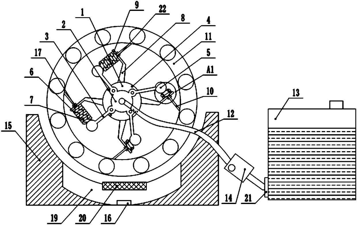
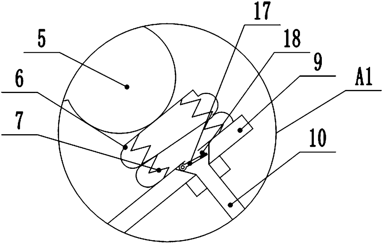
  • Oil injection device for milling machine
  • Oil injection device for milling machine

Examples


Embodiment Construction

[0018] The present invention will be described in further detail below by means of specific embodiments:

[0019] The reference signs in the accompanying drawings of the specification include: support seat 1, oil storage tank 2, oil outlet pipe 3, block 4, hollow pressure ball 5, oil storage bag 6, support spring 7, support rod 8, support plane 9, note Oil pipe 10, bearing 11, oil inlet pipe 12, lubricating oil tank 13, oil pump 14, oil receiving tank 15, recovery port 16, baffle plate 17, magnet 18, oil filter chamber 19, filter screen 20, first sealing ring 21, second sealing Circle 22.

[0020] Such as figure 1 , figure 2 As shown: the oil injection device for milling machine, including the injection mechanism, the injection mechanism includes a support base 1 coaxially connected with the bearing 11 of the milling machine, the support base 1 is fixedly connected with the oil storage tank 2, the oil storage tank 2 is made of rubber material, With elasticity, the oil stor...


PUM


Abstract

The invention relates to an oil injection device for a milling machine. The oil injection device for the milling machine comprises a supporting seat, wherein the supporting seat is coaxially connectedwith a bearing; the supporting seat is fixedly connected with an oil storage bin; a first oil inlet is formed in the oil storage bin; the supporting seat is rotatably connected with an oil outlet tube; one end of the oil outlet tube communicates with the first oil inlet; the end, which is away from the first oil inlet, of the oil outlet tube communicates with a hollow pressure ball; the hollow pressure ball is connected with a retractable oil storage bag; a first oil outlet is formed in a position where the hollow pressure ball is connected with the oil storage bag; a supporting spring is arranged in the oil storage bag; the supporting seat is fixedly connected with a supporting rod; the oil storage bag is fixedly connected to the supporting rod; a second oil outlet is formed in the bottom of the oil storage bag and is connected with an oil injection tube; an oil nozzle is arranged at the other end of the oil injection tube and is abutted to the bearing; the oil storage bin is connected with an oil inlet tube; the other end of the oil inlet tube is connected with a lubricating oil box; an oil receiving groove is formed below the bearing; and a recycling opening is formed in the bottom of the oil receiving groove. The problems that in traditional lubricating oil injection, labor investment is high, and degree of automation is low are solved.

Description

technical field [0001] The invention relates to the field of lubrication equipment, in particular to an oil injection device for a milling machine. Background technique [0002] Milling machine is a machine tool with a wide range of uses. It is mainly used for milling workpieces with milling cutters. It can process planes (horizontal planes, vertical planes), grooves (key grooves, T-shaped grooves, dovetail grooves, etc.), toothed parts on the milling machine. (gears, spline shafts, sprockets), helical surfaces (threads, spiral grooves) and various curved surfaces. In addition, it can also be used to process the surface and inner hole of the rotating body and perform cutting work. When the milling machine is working, the workpiece is installed on the worktable or the accessories such as the indexing head. The main movement of the milling cutter is the rotation, supplemented by the feed movement of the worktable or the milling head, and the workpiece can obtain the required ...

Claims


Application Information

Patent Timeline
IPC IPC(8): B23Q11/12
CPCB23Q11/122
Inventor 欧番
Owner TIANJIN SAIXIANG M&E ENG CO LTD
Learn More